-
Understanding the wire numbers in the patch panel
Look at the back of the patch panel. Each port has a color-coded diagram showing exactly where each wire goes. In the United States, T568B is the standard for the vast majority of. The complete process for terminating cable runs at a patch panel, from mounting and cable management to punch-down, labeling, and testing every port. One commonly used wiring standard is T568B, which provides a standardized method for connecting Ethernet cables.
-
Network patch panel issues
Below is a troubleshooting guide that matches common Ethernet patch panel issues with practical solutions. How to Solve It? Inspect for visible damage and replace faulty cables or ports immediately. Re-route cables properly, use cable managers, and ensure tidy patch panel. Ethernet patch panels are essential components in structured cabling systems, serving as the central hub for managing and organizing network connections in offices, data centers, and other enterprise environments. Terminate each wire according to the T568A or T568B color code. Proper testing helps in identifying issues such as poor. I have just wired all of my homes CAT cables into a patch panel. I plugged an. The problem that I'm facing is, there isn't enough length on some of these and through years of movement of other cables and installation of new AC equipment by maintenance and what-not, I'm slowly losing wired connections for my users. Poor fiber routing, incorrect bend radius, or improper labeling can all lead to signal loss, maintenance difficulties, and unexpected downtime.
[PDF Version]
-
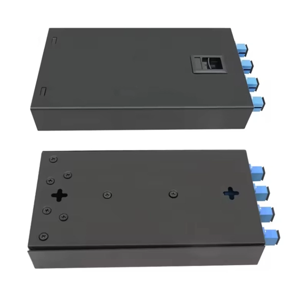
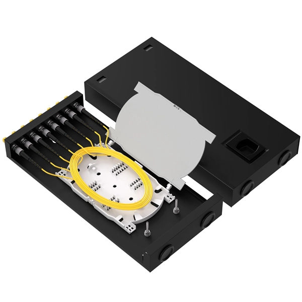
What can be installed on an ODF fiber optic patch panel
Modern high-density panels can support: 12 Ports: Small-scale or edge applications. An ODF is a centralized platform designed for terminating, cross-connecting, and managing optical fibers. It ensures fiber management is structured, minimizes signal loss, and provides accessibility for maintenance and future expansion. ODF Rack/Cabinet: Physical frame housing all terminations and. View our full range of Fiber Optic Patch Panels to browse available configurations, including Rack Mount, Wall Mount, and High-Density ODF solutions. A Fiber Optic Patch Panel, also known as an Optical Distribution Frame (ODF) or fiber termination enclosure, is a centralized hardware unit designed. This 2026 expert guide explains the functions, placement, structure, and application scenarios of ODFs and fiber patch panels-and includes a deep engineering FAQ that resolves real-world deployment challenges. The ODF System Components.
[PDF Version]
-
Network Cabinet Patch Panel Layout Requirements
Our guide delivers actionable, step-by-step best practices for rack layout, cable management, and patch panel installation. Following these steps helps you build a clean and efficient structured cabling system that simplifies maintenance and maximizes network performance. Whether you're upgrading an existing setup or building from scratch, this article helps you make. At Turn-Key Technologies, we design and implement high-performance network setup solutions. We know that a meticulously planned physical layer prevents countless future headaches. Unlike active devices that process data, a patch panel simply provides structured termination points for each Ethernet cable run, creating a clean, scalable. Network cabinet cabling describes the structured connection and arrangement of all IT components in a server rack.
-
How to connect a network module to a patch panel
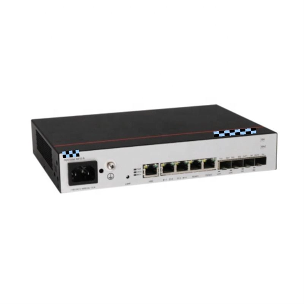
Learn the step-by-step network patch panel and keystone jack wiring methods, including essential tools, T568A/B wiring sequences, and tool-free installation tips. Attach the cable manager to the patch panel port. Note the wiring sequence on the patch panel when wiring, as T568A and T568B. When you're building a network, it's often ideal to use a patch panel to direct cables and organize long Ethernet runs — especially if they go through walls, floors, and/or ceilings. Patch panels make cable management and network organization very easy over long periods of time, but you'll need to. Patch panel and switch are commonly used to connect devices in data centers and telecom rooms, and they are usually mounted on a server rack. Patch panels aren't so difficult to understand but might be a little intimidating at first if you're new to structured wiring. Following these steps helps you build a clean and efficient structured cabling system that simplifies maintenance and maximizes network performance. Before a single cable is.
[PDF Version]
-
How to install a 24-port network patch panel
This video shows how to punch down 24 port patch panel (cat6 patch panel wiring) and also showing Live 15 U network rack mounted on wall equipped with d'link patch panel 24 port, network cable (cat 6 cable) manager and 24 port d'link network switch. So, you purchased all of your shielded solid copper Ethernet cable, shielded keystone jacks, termination tools, and are ready to get your installation started! Finally, a wired network to install your outdoor security cameras rather than relying upon potentially unreliable Wi-Fi. Did you. A patch panel is an essential component in networking, serving as a central point for connecting various network cables. Effective cable management is crucial for maintaining an o. Even as Wi-Fi 6E and Wi-Fi 7 push uplink bandwidth to 5G/10G and. F. This installation guide focuses on what a patch panel does, patch panel installation basics, and how to connect patch panel to switch while keeping cabling. Ubiquiti, Ubiquiti Networks, and the Ubiquiti U logo are trademarks or registered trademarks of Ubiquiti Inc. in the United States and in other countries. All other trademarks are the property of their respective owners.
[PDF Version]