-

Switch cabinet busbar installation
In North America, follow UL 891 construction and NEC Article 408 installation practices: use listed/approved hardware, lugs, or tap-off provisions intended for the bus. The matrix below helps engineers finalize material, arrangement, plating/insulation, and verification. The GRL busbar system makes distribution cabinet installation fast, flexible, and neat. At this stage, the supports have been installed in accordance with the installation plan. Ever wondered how busbars, the unsung heroes of electrical distribution, are processed and installed? This article delves into the intricate steps of busbar selection, preparation, and installation, ensuring efficient and safe power distribution. The application of these rules means strict compliance, not only with applicable regulations and standards, but also with manufacturers'. Bus bars play a crucial role in electrical distribution systems by providing a reliable and efficient way to conduct electricity within electrical panels.
[PDF Version]
-
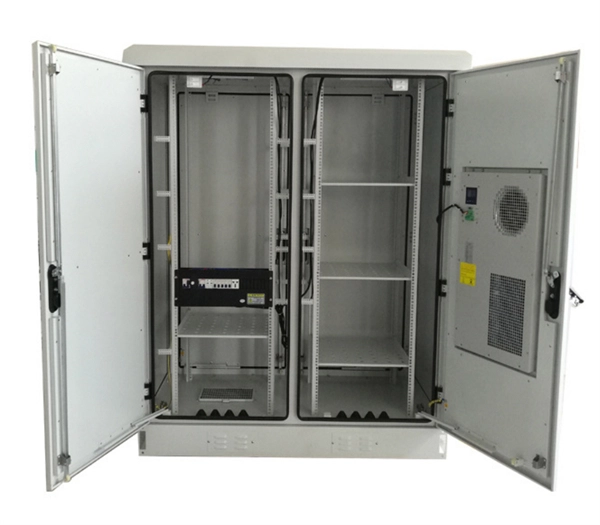
Installation of floor-mounted electrical distribution boxes on construction sites
Browse specifications, literature, drawings, videos and tools that make floor box planning and installation easy. See all our floor box models in one place, including recessed, rectangular, round, and more. Explore live demonstrations and instructional guides in our. Learn how to install a distribution box safely and correctly. It takes the incoming power and safely distributes it to different circuits throughout your building. OTICE – Top end of stakes must be below finished concrete s and seal of unused conduit hub openings with reducer/closure plug LVENT CEMENT MANUFACTURER'S I CTIONS AND SAFETY PRE in 1 oncrete C ve x h with rough floor surfa e. This article details the process of installing them, which helps you comprehend distribution boxes. Walker® electrical systems conform to and should be properly grounded in compliance with requirements of the current National Electrical Code or codes administered by local authorities. All electrical products may present a possible shock or fire hazard if improperly installed or used.
[PDF Version]
-
Standard installation height for household electrical distribution boxes
The proper installation of a distribution box involves placing it at the right height to ensure safety and convenience. This height also safeguards the box from potential. Check for proper IP/NEMA ratings and material quality. Ensure safe placement: install in dry, accessible areas with good ventilation and at appropriate height (typically ~1. Practice good wiring: secure grounding, neat cable management, proper insulation, and correct wire gauge and breaker. The most common question regarding electrical panel installation involves the maximum height allowed for the device. The National Electrical Code (NEC) specifies that the center of the grip of the operating handle of the highest circuit breaker must not be located more than 6 feet 7 inches (2. Ground-mounted foundations should be 50 to 100 mm above ground level.
-
Requirements for Cable Trench and Cable Tray Installation
This article provides a comprehensive framework that governs various aspects of cable tray installations, including the types of cables that are deemed acceptable for use, requirements for grounding and bonding, and stipulations regarding tray fill capacity. Additionally, it addresses critical. NEC Article 392 outlines the key rules for installing and maintaining industrial cable tray systems. These systems, made from metal or plastic, are open structures designed to support electrical conductors, ensuring proper organization and safety. This installation is for underground services from 2001 amps to 4000 amps. The following pages address the 2014 National Electrical Code® requirements for cable tray systems as well as design. Cable tray systems provide a safe, organized, and flexible method for supporting insulated conductors and cables in commercial and industrial electrical installations.
[PDF Version]
-

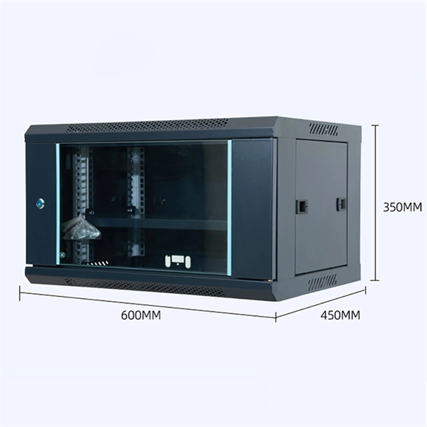
Construction site electrical distribution box installation dimensions and price
This guide covers cost, price ranges, and practical budgeting for standard electrical box installation projects. Cost and price details focus on realistic estimates to help plan a budget. BOSECKER construction site power distributors are designed and manufactured in accordance with the manufacturer standard IEC 61439 and user standard IEC 60364. The robust sheet steel housing has been. BLOCK Series distribution assemblies are made of thermoplastiqc material. This report provides a comprehensive analysis of electrical distribution board (DB) box sizes, including physical dimensions, electrical capacities, and market trends based on current 2025-2026 standards.
-
Installation of galvanized plastic cable trays
This guide covers the critical steps, from selecting the right electrical cable tray and performing accurate cable fill calculations to managing a safe cable pull through and ensuring all bonding and grounding requirements are met. Are you looking for a cost-effective and durable solution for organizing and protecting your cables? Look no further than cable tray galvanized. But before you lay the first tray or clamp down a single cable, you need a solid plan. This guide breaks down the process step by step. The selection of material and finish is a function of the environment in wh tant in a wide range of environments, and easily formable (Appendices II and III). The process described here takes a systematic approach to ensuring that cable tray installations meet safety, reliability, and project-specific needs while following to. Method Statement installation of Cable Trays and Ladders - Planning Engineer FZE.
[PDF Version]