-
How to Choose a Tunable Optical Module SFP 2026
A practical, engineer-friendly guide to choosing the right transceiver form factor by speed, port density, power, migration plan, and operational risk—built for 25G/100G networks in 2026. 25G SFP28 is the new access/server baseline; deploy it for port density and long-term value. 100G QSFP28 is the. Published: 2026 | Category: Network Hardware Knowledge Base / Optical Communications Core Keywords: SFP Module, SFP Transceiver, Small Form Factor Pluggable, What is SFP, SFP vs SFP+ Read Time: Approx. 25 Minutes Even in the era of Wi-Fi 7 and 5G, Optical Transceivers remain the backbone of the. By the Network-Switch. SFP/SFP+: The standard for 1G/10G campus and. SFP-family and QSFP-family transceivers are hot-pluggable modules that convert electrical signals to optical signals (and back) for fiber links in switches, routers, servers, and transport platforms.
[PDF Version]
-
Selection Guide for 40G Tunable Optical Modules for Broadcast Transmission Grade
In this guide, we'll explore the different types of 40G optical transceivers, compare specifications like SR4 and LR4 optics, analyze compatibility with Cisco/Juniper platforms, and provide practical purchasing guidance for enterprises looking to deploy or upgrade their. In this guide, we'll explore the different types of 40G optical transceivers, compare specifications like SR4 and LR4 optics, analyze compatibility with Cisco/Juniper platforms, and provide practical purchasing guidance for enterprises looking to deploy or upgrade their. 40G QSFP+ modules are hot-swappable, quad-lane transceivers that deliver 40 Gbps by combining four 10. 3125 Gbps electrical/optical lanes — the form factor and lane mapping are defined in the QSFP+/SFF specifications. In this guide you will learn: The real differences between the main 40G QSFP+. The 40 gigabit transceiver, particularly the 40G QSFP+ module, plays a pivotal role in modern high-speed networks, especially data centers and enterprise backbones.
[PDF Version]
-
The function of the light guide bar light source module
Through the light diffusion structures on the incidence surface of the light guide bar and the full-reflection action of the light inside the light guide bar, the light guide bar can provide illumination with uniform brightness; and moreover, the utilization rate of. Through the light diffusion structures on the incidence surface of the light guide bar and the full-reflection action of the light inside the light guide bar, the light guide bar can provide illumination with uniform brightness; and moreover, the utilization rate of. The invention discloses a light guide bar and a light source module adopting the same. On a cross-sectional plane of the light guiding bar, there is a first line interval on the upper surface. A second line interval, a third line interval and a. Modern light guides are used for the transportation of light signals from a circuit-board-mounted LED via a particular route to a defined light-emitting surface, with minimal loss and blurring effect. They are used to illuminate areas that are too small or too hazardous to permit the installation of a light bulb.
[PDF Version]
-
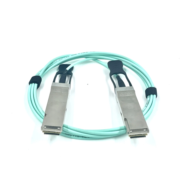
Metro-Grade OTN Router QSFP-DD Selection Guide
This guide provides a clear overview of 400G ZR QSFP-DD standards, specifications, and selection criteria for coherent pluggable optics in metro and long-haul networks. QSFP-DD ZR Coherent Optics presents a sea of change in the field of optical transportation architecture. The product supports 100Gbps transmission speeds in an. The QSFP-DD OLS is a pluggable open line system solution that can be directly hosted on a Cisco router. The Cisco® QSFP-DD Open Line System (QSFP-DD OLS) is a pluggable optical amplifier module that, together with the channel breakout options (described later), provides a simple yet powerful open. The 4. The DP01QS28-E20 and DP01QS28-E25 transceivers enhances the Routed Optical Networking solution by adding a 100G-only tuneable optic which be used across both. Quad Small Form-factor Pluggable Double Density (QSFP-DD) solution that fits into high-density switch and router client ports for optical interconnect links Powered by Greylock and Delphi DSP ASICs, and silicon photonic integrated circuits (PICs) for an optimized co-packaged design with 3D.
[PDF Version]
-
10 Gigabit Ethernet card optical module not connected to fiber optic cable
Troubleshooting SFP+ link issues in 10 GbE networks requires attention to module type, match of speed and wavelength, clean fiber connections, correct configuration, thermal management, and equipment compatibility. You can quickly resolve SFP+ Module connectivity issues by following a systematic optical transceivers troubleshooting process. Check for common connection problems, such as link failures or modules not recognized. Check compatibility between the optical module and switch Most switch brands have specific compatibility requirements. During network upgrades, many enterprise users encounter a common issue: after replacing 10G broadband lines or inserting 10G SFP+ optical modules, the switch still fails to operate at full 10G bandwidth or even fails to recognize the modules. We've listed the five most common ones. First of all, let's briefly recap what SFP and SFP+ stand for. SFPs – short for 'small form-factor pluggable' – are compact, hot-pluggable devices.
[PDF Version]
-
How to connect the SD signal in the 19 optical module
The unit accepts one SDI signal on a BNC connector and provides one optical output of this signal on an ST connector over single-mode cable with a 1310 nm wavelength. solution for virtually any conversion you could need. Mini Converters convert analog to digital, digital to analog, SDI to audio, audio to SDI, up, down and cross conversion, SDI distribution, and can even provide a sync generator for lockin all your video equipment to the same reference signal. These transceiver modules are hot-swappable input/output (I/O) devices that plug into 100BASE, 1000BASE and 10GBASE ports (for SFP+), which connect the module port with the fiber-optic or copper network. If the optical module is installed on a GE port, run the display interfaceGigabitEthernet x/x/x command to view port information when the optical module. When the optical module on an interface is faulty, you can run the display commands to view information about the optical module. The notices referring to your personal safety are highlighted in the manual by a safety alert symbol, notices referring only to property damage have no safety alert.
[PDF Version]
-
What skills are needed to make an optical module
Optical engineering relies heavily on math and physics concepts, such as geometry, trigonometry, calculus, linear algebra, differential equations, optics, electromagnetism, quantum mechanics, and thermodynamics. btained theoretically but also through scientific process skills. This study aims to 1) Produce an optical module based on a science process skill approach, 2) Know the quality of an optical. As technology continues to advance, the skill of designing optical systems has become increasingly relevant in the modern workforce. Optical systems play a crucial role in a wide range of industries, including telecommunications, medical imaging, aerospace, and more. Their work often involves a combination of theoretical physics, computer-aided design, and practical experimentation. As an optical engineer, you may work on projects involving lasers, lenses, mirrors, fiber optics, cameras, displays, sensors, or other applications of light.
[PDF Version]
-

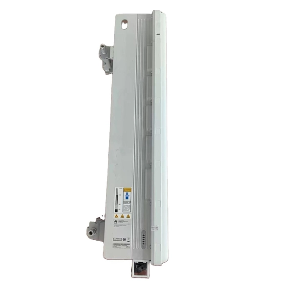
RRU optical module location
RS can be installed in a suitable machine room location, and RRU is installed at the antenna end. By separating RS from RRU, the tedious maintenance work can be simplified to the RS end. AAU, RRU, and BBU are key components in a telecom network, particularly in modern wireless communication systems like 4G and 5G. Here's a breakdown of each: The central processing unit in a base station. Usually. Optical modules used in Remote Radio Units (RRUs) for CPRI applications are required to support industrial temperature ranges, primarily because RRUs operate in diverse outdoor environments with extreme temperature variations. CPRI (Common Public Radio Interface) defines the interface relationship. RRU is short for remote radio unit. Strip the jacket off the RRU power cable for a small part, press the exposed shielding layer on the strap, and then connect the PGND cable on the strap to the nearest grounding bolt on the side in the. The mode. Determine a position for installing 2. Loosen the two M10 nuts on the mounting M10 bolt from the U notch.
[PDF Version]
-
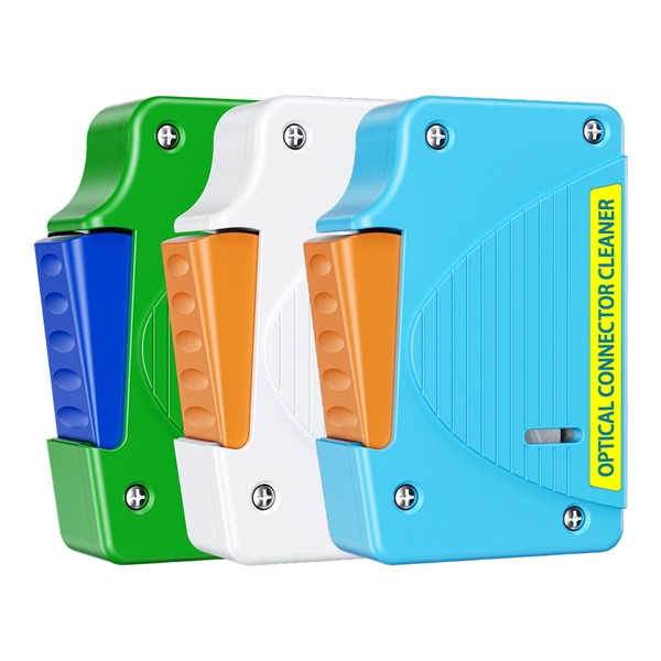
How to enable the optical module after plugging it into the optical port
Align the SFP module with the optical port and insert it horizontally, pressing firmly until the bottom of the module engages with the locking spring of the optical interface. Figure 1 SFP Optical Module Installation. The Cisco Small Business Series Switches allow you to plug in a Small Form-factor Pluggable (SFP) transceiver in their optical modules to connect fiber optic cables. Once the transceiver and fiber optic cable are plugged in properly in the switch optical module, you should be able to view the. This section describes how to install optical transceivers on the SFP or SFP+ ports and connect them to the ports of the peer device using optical fibers according to the network plan. The USG supports both 1 Gbit/s, 10 Gbit/s, and 40 Gbit/s optical modules. The LED will only light up when all connections are properly established and functioning correctly. The installation process can be taken by the following instructions.
[PDF Version]