 Guide
Guide FIBER OPTIC MEASUREMENT TECHNIQUES
EIA/TIA-455-47 describes various procedures, or methods, for measuring the far-field power distribution of optical waveguides. These procedures involve either an angular or spacial scan.
 Guide
Guide Fiber Optic System Testing Tutorial
Prevailing measurement methods include source-meter end-to-end loss measurements, as well as optical time domain reflectometer methods. The remaining sections of this document
 Guide
Guide Reference Guide to Fiber Optic Testing
Others require access to only one end. Measurement techniques that require access to only one end are particularly interesting for field applications since these measurements reduce the time spent
 Guide
Guide TSB-140: Additional Guidelines for Field-Testing Length, Loss and
The TIA FOTC provides an overview of TSB-140 Additional Guidelines for Field-Testing Length, Loss and Polarity of Optical Fiber Cabling Systems.
 Guide
Guide Fiber Optic Measurement Procedures | Kingfisher International
Application note: Overview of practical fiber optic loss measurement concepts, procedures and practice for all types of fiber systems.
 Guide
Guide Measurements in New Optical Cables Pre-Construction and Post
Lead-in fibers are useful to locate short distance faults and making loss/attenuation measurement in real time mode. This document explains how to use lead-in fibers. Optical fiber cables are tested for
 Guide
Guide Fiber Optic Testing Standards
An Optical Power Meter and Laser Light Source will be used to measure power loss on each completed ring or distribution span to verify continuity between fibers (no fibers incorrectly spliced together).
 Guide
Guide Fiber testers : Equipment and tools | Fluke Networks
What is fiber optic testing? Fiber testing is the process of verifying the performance of optical fiber cabling. This process includes a range of tests and measurements such as insertion loss, optical
 Guide
Guide GENERAL INFORMATION
Field testing fiber optic cables can be done with different types of equipment. Most test procedures for this equipment have been standardized by national standards bodies such as TIA
 Guide
Guide NIST Optoelectronic Measurements for Fiber Optic Applications
NISTcurrently has optical fiber measurement fforts in polarization moded spersion, fiber diameter, andmode-field diameter, andt aceability for these measurements is enabled through Reference
 Guide
Guide The FOA Reference For Fiber Optics
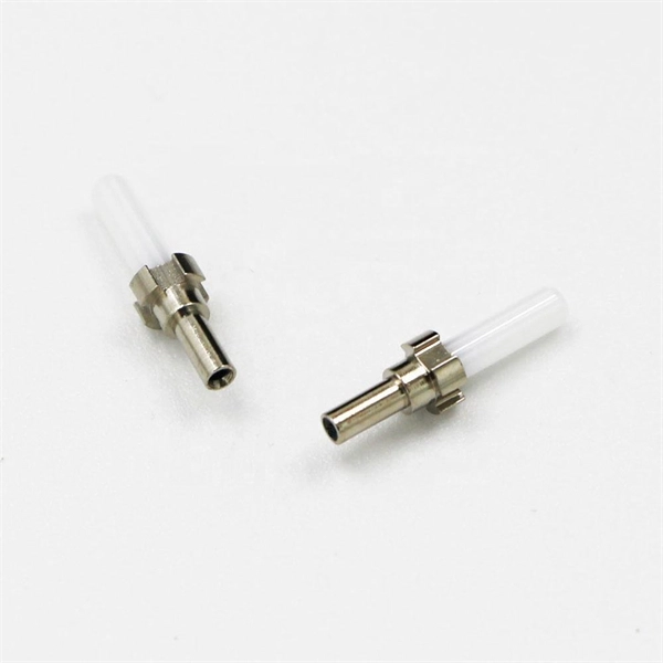
The best method is to use a bare fiber adapter on the power meter to measure the output of the bare fiber, then attach the splice. Alternately, have the splice attached on the pigtail and couple a fiber to