-
What is the fiber optic splice tray in the optical distribution box
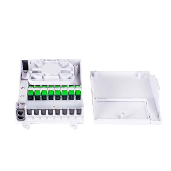
• Splice Tray: This compartment is designed for fiber splicing and storage. It features slots or holders that secure spliced fibers, protecting them from bending, physical damage, or external stress. What is a Fiber Splice Tray Used for? With the increasing development of optical fiber networks, optical fiber terminals using fusion splicing or mechanical fusion have become common. Because optical fibers are sensitive to pulling, bending, and crushing forces, use fiber splice trays to provide. With the growth of FTTH, FTTx, and telecom fiber networks, the management of fiber optic splicing plays an increasingly important role in network reliability, performance, and maintainability. Inside splice closures, cabinets, and distribution frames, dozens or even hundreds of fibers need to be. Fiber Distribution Boxes (FDBs) are critical components in modern telecommunications infrastructure, particularly in fiber optic networks. Typically made from durable materials like plastic or.
[PDF Version]
-
Length of grounding rod in optical distribution box
For a driven rod electrode, Rule 094B2 requires the rod to be 8 ft in length and driven to a depth of 8 ft below the ground level. (1) Grounding Conductors: The grounding conductors of the communication messenger system shall conform to each of the following requirements: a) The grounding conductor from each ground rod (ground electrode) to the base of the pole shall not be less than 1 foot below the surface of the ground. SEC Distribution System extends from the MV (33 kV, 13. 8 kV) feeder outlets of HV/MV Substations down to SEC Customer interface including KWH-Meters and meter boxes. To. Power from factory ground must be installed by a qualified electrician. Each DISTRIBUTION BOX and controller must be grounded. Ground rods shall be installed at least two feet from the face of the pole, with the tops of the rods at least 12 inches below ground.
[PDF Version]
-
Israeli High-Temperature Resistant Optical Cable Patch Cord Price CIF
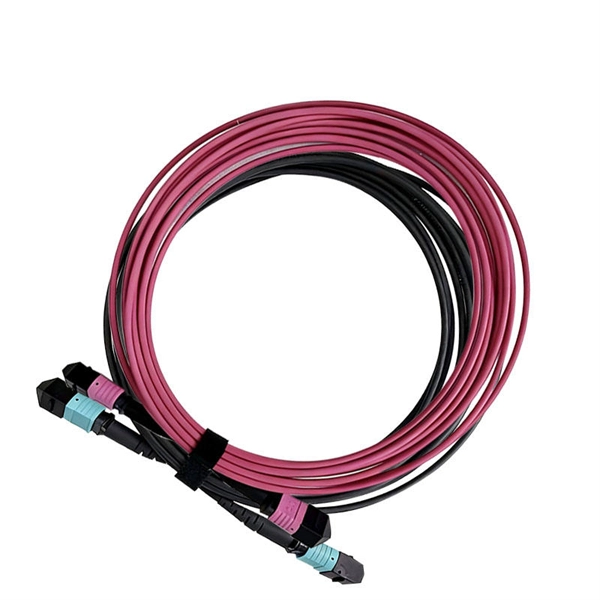
Mouser offers inventory, pricing, & datasheets for Patch Cord Fibre Optic Cable Assemblies. 1mm, heatherviolet, OM4 Fibre Optic Cable. Indeed, we have designed high-temperature cables for applications ranging from 150 °C to 1000 °C. Length: from 20 m to 100 m depending on the buffer type (up to +500 °C), or 2 m maximum at +1000 °C. Thorlabs' Ultra-High-Vacuum, High-Temperature Multimode Fiber Optic Patch Cables, part of our vacuum-compatible product line, are designed for use in UHV environments at pressures as low as 10-10 Torr and continuous operation in high-temperature environments up to 250 °C. Low-loss, durable connections for telecom & networking. Compared with the traditional fiber optic cabling solutions, this high-density fiber optic solution offers higher flexibility and space-saving while supporting. The Most Extensive, Most Varied, Highest-Quality Inventory in Israel We market and sell cabling from a catalog that includes more than 8,000 imported products, manufactured by the leading companies in their field, represented by us in Israel. These products meet the standards: UL, MIL-STD, CE, and.
[PDF Version]
-
Customization Process for Low-Noise Fiber Optic Distribution Frames for Broadcast Transmission
This complete guide explores everything you need to know about ODFs — from their structure, types, and key components, to installation best practices and modern design trends. It includes first determining the type of communication system (s) which will be carried over the network, the geographic layout (premises, campus, outside. An Optical Distribution Frame (ODF) is the central hub for fiber splicing, termination, patching, and cable protection in modern optical networks. Why do operators, designers, and installers use additional fiber optic hardware racks for cable and fiber management? The active electronics are the most expensive part of the.
-
Calculation of the number of network patch panels
As a rough guideline, most organizations install between 24 and 48 ports per patch panel and use a maximum of four to six patch panels per rack. Basic Concepts and Classification of Fiber Optic Patch Cords Fiber optic patch cords are fiber cables terminated with. Some of the key considerations include: Number of ports: Choose a patch panel with the right number of ports to accommodate your network devices. Mounting options: Consider the mounting options for the. A patch panel is a hardware device that connects multiple network circuits in a central location, which acts as a hub for all network connectivity. When it comes to patch panels per rack, there is no hard and fast rule. It all depends on the requirements of the organization or the enterprise. For example, for structured cabling that might "want" wall-mount patch panels on either end of pieces of conduit, combined with in-rack patch panels. A bulk (multi-strand) fiber cable enters the patch panel and then each fiber strand is separated into individual strands or pairs of strands.
[PDF Version]
-
What type of copper is used in network patch panels
Twisted-pair copper patch panels are built to a certain Ethernet specification, such as Cat 5e, Cat 6, or Cat 6a, and though they are backwards compatible, use different gauges of copper wiring to facilitate the greater bandwidth and shielding of the higher categories. In each case, the patch panel. Today, various styles of copper patch panels can be found in the market, such as shielded or unshielded patch panel, flat or angled patch panel, etc. Their design, material, and compliance directly affect signal integrity, insertion loss, crosstalk, manageability, and fire safety.
-

How to configure fiber optic patch panels in a computer room
Our guide delivers actionable, step-by-step best practices for rack layout, cable management, and patch panel installation. Following these steps helps you build a clean and efficient structured cabling system that simplifies maintenance and maximizes network performance. How to Install Fiber Optic Patch Panel Only by taking the proper steps can achieve a reliable network. A successful project begins with careful planning. Before a single cable is. In modern data centers, where high-speed and high-density connectivity is critical, organizing fiber optic patch panels effectively is essential for performance, scalability, and maintenance. Here's a step-by-step guide to help you properly arrange fiber optic patch panels in a data center. In this section, the common steps for connecting patch panels with fiber optic cables or network switches will be demonstrated.
[PDF Version]
-
How are fiber optic patch panels fixed
The cable is fixed using clamps or strain relief mechanisms to prevent movement or tension on the fibers. Inside the patch panel, fibers are terminated in one of two ways: The terminated fibers are then routed to the front panel adapters. These individual strands will then connect to electronic devices. How does a slide-out patch panel differ from a fixed panel? A slide-out patch panel features a drawer-like mechanism allowing the internal tray to be pulled forward, providing technicians easy access to internal splices and rear connectors without disrupting adjacent equipment. This article explores the structure, functionality, types, and benefits of fiber optic patch panels.
-
The function of installing network modules into patch panels
Patch panels serve as the backbone of structured cabling systems, providing a centralized point for organizing and connecting network cables. They come in a range of sizes, and are typically mountable, whether that's on a wall, or on a rack to make for easier. Quick Definition: A patch panel is a crucial network component that helps in the connection, organization, and overall management of network cables. It acts as a central point for neatly labeling and laying out all network cables, preventing tangled knots of CAT5 cables in a Local Area Network. The type of patch panel you select must match your network's performance requirements. The patch panel is designed to work with specific cable types, and a mismatch will create a bottleneck. Whether deploying a small. Both work on the same principle, using the module's built-in clips to press the network cable directly into the module's wire clamps, eliminating the need for punching down steps. (*Our company's account name is " Cobtel Precision Electronics Co. " Please carefully verify beneficiary's name.
[PDF Version]
-
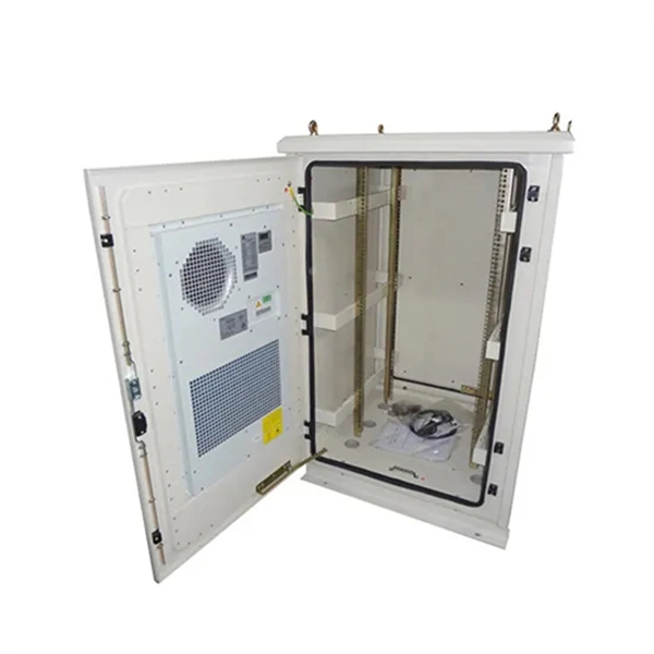
Composition of optical distribution box
It is widely adopted in FTTx cabling for both fiber cabling, provides the connection between fiber optic cables and passive optical splitters. Fiber Distribution box contains the shell, the internals (supporting frame, set fiber disc, fixing device) and optical fiber. The fiber distribution box, a crucial component in optical fiber networks, serves a dual purpose of managing and protecting optical fibers while facilitating their efficient distribution. Whether you're building a central office, data center, or FTTx distribution network, understanding the right ODF. ication and relevant standards over the range of optical wavelengths from 1260nm to 1625nm. However, component desi n should also take account of future requirements to extend operating wavelength to 1675nm. Cross-con-nections and direct connection can be two ways to.
[PDF Version]