-
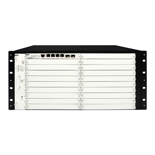
Six-Column Relay Protection Tester
Specifically designed for settings-based protection testing with a high degree of automation, our modular software Test Universe offers numerous functions and application-optimized test modules that save yo.
-
Microcomputer Testing of Relay Protection
For testing high-voltage microcomputer protection devices, it is recommended to use a microcomputer relay protection tester capable of simultaneously outputting three-phase voltage and three-phase current, and equipped with timing function for digital inputs. Meet all test requirements on site. It can test not only various traditional relays and protection devices, but also various modern microcomputer protections, especially for transformer differential protection and. Protective Relay Test Set, Relay Tester, Secondary Current Injection Test Kit, Microcomputer Protection Testing, 3-Phase Relay Tester Discover why selecting the right Protective Relay Test Set is critical for microcomputer protection verification. In this paper, the characteristics of the equipment itself and the external environment are comprehensively considered, and.
[PDF Version]
-
Several characteristics of relay protection are
To provide effective and reliable protection to the power system, a protective relay must have the following essential functional characteristics: Selective, Fast, Stable, Reliability, Sensitivity, Simple Construction and Installation Mechanism, and Cost-effective. A protective relay is an electrical switch which can automatically operate when a fault or any other abnormal conditions occur in the electrical system. It sends a signal to turn on the alarm or indicator or trip a circuit breaker to separate the faulty part from the healthy section. : 4 The first protective relays were electromagnetic devices, relying on coils operating on moving parts to provide detection of abnormal operating conditions such as. A protective relay is an intelligent electrical device designed to detect faults in power systems and initiate corrective actions such as tripping a circuit breaker. PSM – Plug Setting Multiplier (Current Setting Multiplier) What is PSM? 2).
[PDF Version]
-

Relay Protection Test Wiring Method
One approach to test the total protection system is to use primary injection techniques (see appendix H) that trigger protective relays and lockout relay, trip circuit breakers, and initiate annunciations and indications. If applicable, documentation is required detailing how verified protection segments overlap to ensure there is not a gap. The purpose of this Standard Work Practice (SWP) is to standardise and describe the method for testing of Ergon Energy protection relays for commissioning purposes. This SWP should be interpreted in conjunction with Standard for Substation Protection (V1. From a technician's perspective, master the unique skill of testing protection. When the transformer wiring type is Y/Y (Y0), the test wiring is very simple: when testing phase A, the tester IA is connected to the phase A of the high voltage side, and the tester IB is connected to the phase a of the low voltage side. After the neutral line of the high and low voltage sides is. Function: Use electronic components like transistors to perform switching. Applications: Frequency, undervoltage, and overcurrent protection.
[PDF Version]
-
Is it dangerous to repair relay protection
Doing so may result in reducing Relay performance for insulation failure, contact welding, and contact faults, and might even result in burning or other damage to the Relay itself. Do not drop the Relay or dismantle it. Refer to the Safety Precautions for individual Relays for precautions specific to each Relay. Electric shock may. A relay that is correctly set for yesterday's system may become a serious risk after a plant expansion or load change. This article breaks down the most common protection relay misconfigurations in industrial facilities, why they happen, and how they impact system reliability and operational. onding to faults, ensuring the reliability and stability of the grid. However, unauthorised changes to protection relay settings pose a significant threat to the integrity of power systems. Although failure of a protective relay system may have severe local or regional impacts, most protective relay systems are not required to operate to prove they are in working order.
[PDF Version]
-
Requirements for Relay Protection Design
The IEEE standard for protection relays refers to a collection of guidelines developed by the Institute of Electrical and Electronics Engineers. This document provides recommendations, background and philosophy on relay protection that is not available in M07. They are intended to quickly identify a fault and isolate it so the balance of the system continue to run under normal conditions. For professionals working in utilities, industries, or renewable energy systems, understanding these standards is not optional—it is essential. This handbook covers the code of practice in protection circuitry including standard lead and device numbers, mode of connections at terminal strips, colour codes in multicore cables, dos and donts in execution.
-
Steps for replacing the CPU module of a relay protection device
Learn the essential steps for safely removing and reinstalling a PLC CPU module to prevent equipment damage, data loss, or safety hazards. Always consult the manufacturer's documentation for model-specific instructions. Incorrect wiring may result. 1. 1 INTRODUCTION TO THE UR The GE Universal Relay (UR) series is a new generation of digital, modular, and multifunction equipment that is easily incorporated into automation systems, at both the station and enterprise levels. The application software. Manual intended for personnel responsible for installing, commissioning and using VIP protection 400. The following steps outline best practices, but always consult the. This handbook covers the code of practice in protection circuitry including standard lead and device numbers, mode of connections at terminal strips, colour codes in multicore cables, dos and donts in execution.
[PDF Version]
-
Intermediate relays are commonly used in relay protection
Intermediate relay: used in relay protection and automatic control systems to increase the number and capacity of contacts. Its main function in an electrical control system is to carry. What is an Intermediate Relay? The intermediate relay is a low-power device for activating higher-power circuits. We can also call it an interposing relay. Depending on the application—whether for signal amplification, overload protection, safety shutdown, or high-frequency switching —different types of relays are used.
-
What are the main functions of electrical secondary relay protection
These devices detect abnormal operating conditions and initiate protective actions to isolate faults and prevent equipment damage. In other words, the prime function of protective relays is the timely and. Current transformers step down the monitored current to a secondary (output) range of 0 to 5 amps AC to power the protective relay. This prevents damage to equipment, reduces. A protection relay is an intelligent device used to monitor electrical parameters such as current, voltage, frequency, and phase angle.
-
Conventional Relay Protection Functions and Principles
The article provides an overview of protective relaying principles and their applications for high-voltage power system components. It covers the protection methods for generators, transformers, buses, and transmission lines using various relay types to detect and isolate faults efficiently. The. Also proficient in system modeling and studies with EasyPower and EMTP. Currently residing in Denver, Colorado. Based on Operating Principle Electromechanical Relays: Work using moving parts and electromagnetic forces (traditional.
-
Calculation of State Grid Relay Protection
Use this Protection Relay Setting Calculator to calculate pickup current, time multiplier settings (TMS), operating time, coordination time interval (CTI), and plug setting multiplier (PSM) using fault current, CT ratio, and IEC 60255 curve parameters. To adapt the grid to the requirements of intelligentization and the dispatching and control cloud technology route, this paper proposes a relay protection setting calculation method for power grid based on distributed parallel computing. These calculations are critical in industrial. The selected protection principle affects the operating speed of the protection, which has a significant im-pact on the harm caused by short circuits. The faster the protection operates, the smaller the resulting ha-zards, damage and the thermal stress will be.