-
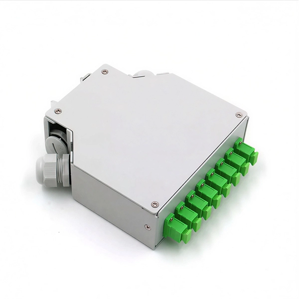
Dutch fiber distribution box 24 cores
Supports 24-core splicing capacity, ideal for high-density FTTx applications. Accommodates up to 4x1:8 tube splitters for efficient signal distribution. Special-shaped lock provides secure access and superior waterproof performance. Optimized for FTTx networks, connecting drop cables to feeder cables for up to 24 users. Inquiry Now! Add to Basket Customization Options. 1. who are we? We are based in Zhejiang, China, start from 2014,sell to Southern Europe (25. how can we guarantee quality?This distribution box terminates up to 2 fiber optic cables, offers spaces for splitters and up to 48 fusions, allocates 24 SC adapters and working under both indoor and outdoor environments. It is widely used in residential buildings, business centers, and villas, providing an efficient solution for last-mile. We accept various payment methods, including credit/debit cards (Visa, MasterCard, American Express), PayPal, and other secure online payment gateways.
[PDF Version]
-
How many optical fibers can a fiber optic terminal box connect to
It integrates a splice tray, pre-terminated drop cables (1, 2, 4, or 8 fibers), fiber patch cords, and shutter-type adapters in one compact enclosure. An Access Terminal Box (ATB), also known as a fiber access socket or fiber pizza box, is an indoor optical connection device used to link fiber drop cables with the optical distribution network (ODN). Built with an IP65-rated enclosure, this terminal box is designed to withstand harsh environments, making it suitable. FTB max for mass deployment in residential units – terminates 168 fibers in a compact design.
-
How to use a red light power meter
Lets say you are a light therapy enthusiast that wants to take your own proper measurements. Or you bought a red light therapy product and want to verify it meets outputs the intensity that it claimed. Then.
-
How to Choose a Tunable Optical Module SFP 2026
A practical, engineer-friendly guide to choosing the right transceiver form factor by speed, port density, power, migration plan, and operational risk—built for 25G/100G networks in 2026. 25G SFP28 is the new access/server baseline; deploy it for port density and long-term value. 100G QSFP28 is the. Published: 2026 | Category: Network Hardware Knowledge Base / Optical Communications Core Keywords: SFP Module, SFP Transceiver, Small Form Factor Pluggable, What is SFP, SFP vs SFP+ Read Time: Approx. 25 Minutes Even in the era of Wi-Fi 7 and 5G, Optical Transceivers remain the backbone of the. By the Network-Switch. SFP/SFP+: The standard for 1G/10G campus and. SFP-family and QSFP-family transceivers are hot-pluggable modules that convert electrical signals to optical signals (and back) for fiber links in switches, routers, servers, and transport platforms.
[PDF Version]
-

How to ground the scaffolding distribution box
26 mm 2 (10 AWG) ground wire must be used, and in all other markets a 6 mm 2 must be used. On the US market, a 5. Each DISTRIBUTION BOX and controller must be grounded. Grounding of the units: Attach a ground wire from one of. Scaffoldings are grounded to ensure that any stray electrical current is safely diverted into the earth, preventing accidental electrocution, fire hazards, and static discharge on construction sites. This device safely takes power from a single source, such as a generator or temporary utility service, and divides it into. To ground a subpanel in a detached building, pull 4 conductors and separate the grounded and grounding bus. This part is covered by National Electrical Code article 250. Paragraph (d) of this section also applies to protective grounding of other equipment as required elsewhere in this Subpart.
[PDF Version]
-
How to bring the pigtail out of the junction box
In this step-by-step guide, we will explore the process of replacing a pigtail connector. This article will walk you through the necessary steps and provide. The instructions say to wrap the wires from my junction box around the screws on the back of the lampholder But the wires coming out of my junction box are all pigtailed, making it impossible to wrap them around the screws Take another piece of wire (called a pigtail) and twist it in with the. In this article, you'll learn how to splice a single gang junction box. A single gang electrical box (one gang box) is where electricians install a switch, plug, or thermostat! We splice wires in the box to carry on power (junction box), or use switch legs to turn a light on or off. A 'pigtail' is simply an extension that is added to a piece. The National Electrical Code (NEC) limits " box fill," aka how much you can stuff in there. Below, I'll show you how to do it, too. To remove a junction box, you typically need to turn off the power, assess its mounting.
[PDF Version]
-
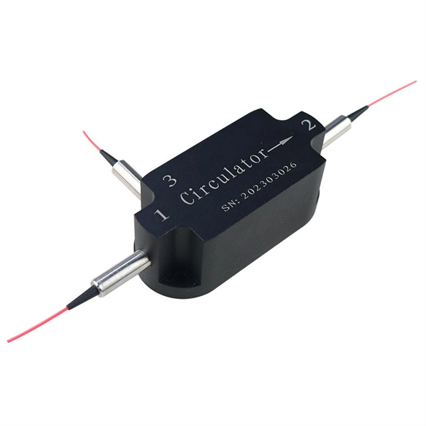
How to test the continuity of pigtail fiber
A visual fault locator (VFL) makes use of a visible spectrum laser light to test the continuity of the fiber and detect fault conditions. There are two reasons we may want to test bare fiber, by that we mean fiber that has not been terminated in connectors but is simply plain optical fiber, The first one is to ensure the fiber or cable being manufactured meets its specifications, as is done by every manufacturer. Fiber optic. The Optical Time Domain Reflectometer (OTDR) will be used to test splice loss and to conduct span analysis. An Optical Power Meter and Laser Light Source will be used to measure power loss on each completed ring or distribution span to verify continuity between fibers (no fibers incorrectly spliced. A visual check is often the first step when diagnosing a defective fiber pigtail. Continuity testing verifies that the fiber is intact and that light can pass through from one end to the other without any blockages. This comprehensive guide will equip you with the knowledge and skills to accurately assess the integrity of a pigtail, helping you identify issues.
[PDF Version]
-
How far apart should the cable tray be placed with its fixed support
Support spacing for cable trays must align with the manufacturer's instructions, as outlined in NEC 392. Generally, standard trays require supports every 6 to 10 feet, while heavy-duty, long-span trays can handle distances of up to 20 feet between supports. The NEC has a requirement for ladder-type cable trays. This is a description of how to select, install, and support these metal or plastic frames, on which electrical wires are installed. You should consider it as a series of instructions that make the buildings resistant to. When installing two cable trays in parallel at the same height, the distance between them should be no less than 0. But it's also important to minimize.
-
How to route fiber optic cables for high-voltage power lines
This technique takes a small, lightweight fiber optic cable and wraps it around or lashes it to the power line. The cable is called optical power attached cable (OPAC), and it is lashed to the power cable with a specialized tool that is pulled from the ground, such as a. Installing ADSS (All-Dielectric Self-Supporting) cables near live power lines demands precision, compliance with safety standards, and an understanding of high-voltage risks. This guide from GL FIBER breaks down the process into actionable steps, aligned with IEEE 524 and IEC 61935-1 protocols, to. Most aerial fiber optic cables are installed by lashing to a steel messenger wire strung between poles, but there is a category of cables with special high-strength jacket designs called all-dielectric self-supporting (ADSS) cables. ADSS cables are designed to withstand very high-tension loads. bles in a high voltage environment, with typical line voltages of 115 kV or more, requires the evaluation of certain critical parameters. Curr ntly, there are a limited number of industry documents that address the requirements for optical fiber cables near high voltage circuits.
[PDF Version]
-
How is the silicon photonics module industry
The market encompasses silicon-based photonic components, integrated photonic devices, and system-level products utilized across various applications, including data communication, computing, defense, medical and life sciences, automotive, and industrial sectors. 16 billion in 2024 and is projected to reach USD 9. Silicon photonics is experiencing strong growth due to the increasing demand for high-speed data transmission in AI, cloud computing. The global silicon photonics market size was valued at USD 3. 83% during the forecast period. Explosive AI/ML. Yole Group unveils its latest photonic market and technology analyses, Silicon Photonics 2025 and Co-Packaged Optics for Data Centers 2025, which explore how AI-driven demand is reshaping connectivity, from transceivers to packaging innovation. 200G/channel will become the new mainstream, enabling.
[PDF Version]
-
How to secure a low-hanging optical cable
All cables must be securely lashed to the messenger and/or cable (s) with no loose hanging cables anywhere along the span. Messenger wire must be neatly terminated at the ends. ons, and company safety practices and policies. Failure to do so can result in life-threat t truck or on a ladder so that it cannot fall. Use the leather gloves when. The Fiber Optic Association, Inc. The charter of the FOA was to promote professionalism in fiber optics through education, certification, and. Deploying fiber above ground on poles or towers removes the need for underground digging and is particularly useful when the ground is uneven, rocky or both. The methods described are intended for guideline use only, as it is impossible to cover all the various conditions that may arise during an installation. Individual company practices for placing. “Securing” fiber optic cable goes beyond just preventing it from moving; it encompasses protecting its delicate core from physical stress, environmental degradation, and ensuring long-term signal integrity.
[PDF Version]