-
How to read the wavelength of a source optical module
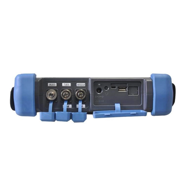
In fiber optic networks, accurately identifying the wavelength of an optical transceiver module is essential for ensuring optimal network performance and reliability. One of the most effective and widely used methods is through the pull-tab color on transceiver modules. This simple visual system. That's where an Optical Spectrum Analyzer (OSA) comes in—a powerful instrument that measures the wavelength, power, and spectral characteristics of light. Think of it as a "microscope for light," revealing details invisible to the naked eye. We all know that CWDM has a total of 12 wavelengths, with a full band range of 1270-1610nm, with each wavelength interval of 20nm. SFP+: small form-factor pluggable plus, SFP with a higher rate. Considering that some newcomers to optical modules may not understand the letters on the optical module or the. Optical power, required for measuring source power, receiver power and, when used with a test source, loss or attenuation, is the most important parameter and is required for almost every fiber optic test.
[PDF Version]
-
The function of the light guide bar light source module
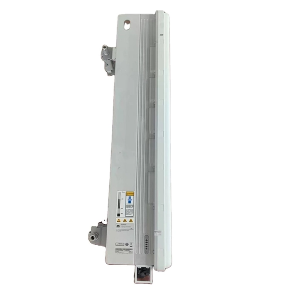
Through the light diffusion structures on the incidence surface of the light guide bar and the full-reflection action of the light inside the light guide bar, the light guide bar can provide illumination with uniform brightness; and moreover, the utilization rate of. Through the light diffusion structures on the incidence surface of the light guide bar and the full-reflection action of the light inside the light guide bar, the light guide bar can provide illumination with uniform brightness; and moreover, the utilization rate of. The invention discloses a light guide bar and a light source module adopting the same. On a cross-sectional plane of the light guiding bar, there is a first line interval on the upper surface. A second line interval, a third line interval and a. Modern light guides are used for the transportation of light signals from a circuit-board-mounted LED via a particular route to a defined light-emitting surface, with minimal loss and blurring effect. They are used to illuminate areas that are too small or too hazardous to permit the installation of a light bulb.
[PDF Version]
-
Gocent optical module
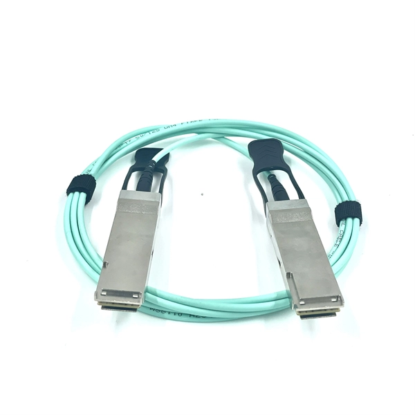
Coherent optical module refers to a typically hot-pluggable coherent optical transceiver that uses coherent modulation (BPSK/QPSK/QAM) rather than amplitude modulation (RZ/NRZ/PAM4) and is typically used in high-bandwidth data communications applications. Optical modules typically have an electrical interface on the side that connects to the inside of the system and an optical int. Electrical Interface TypesThere are multiple variants of the electrical interface of coherent optical modules use. The in 2016 published the CFP2-ACO or CFP2 - Analog Coherent Optics Module Interoperability Agreement. Many different forms of optical modulation and multiplexing have been employed in coherent optical modules. Some coherent optical modules can fall back to older, simpler modulation techniques.
-
Which device should the optical module be plugged into
Optical modules can either plug into a front panel socket or an on-board socket. The optical module serves as a crucial component in optical fiber communication systems, operating at the physical layer, which is the lowest layer in the OSI model. Its primary function is to achieve optoelectronic conversion by converting electrical signals into optical signals and vice versa. Optical modules typically have an electrical interface on the side that connects to the inside of the system and an optical interface on the side that connects to the outside. The QSFP-DD, QSFP, and SFP transceiver modules are hot-swappable and connect the electrical circuitry of the system with an optical external network. The following figure shows the QSFP-DD transceiver, but the procedures outlined in this document apply to all pluggable transceivers. To aid in the task of choosing the right transceivers for your network, here are 6 key factors that should be reviewed with a transceiver/networ system specialist before making your final selections. These technical and operational.
[PDF Version]
-
How to connect the 10 Gigabit Ethernet cable to the fiber-to-electrical port module
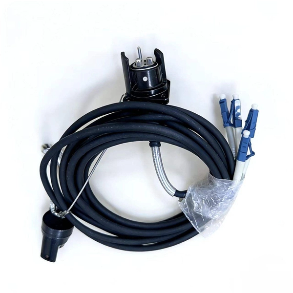
A special 10G Copper RJ-45 Transceiver (10G-SFP-T) is required to connect the SFP+ port to RJ45. It allows connecting a server/storage side Cat6/7 cable to an SFP+ port transceiver. An SFP module (or optical transceiver) converts electrical signals from network devices (switches, routers) into optical signals for fiber transmission and vice versa. 1G/10G SFP+: Standard for Gigabit and 10 Gigabit Ethernet. These transceiver modules are hot-swappable input/output (I/O) devices that plug into 100BASE, 1000BASE and 10GBASE ports (for SFP+), which connect the module port with the fiber-optic or copper network. 4ft (30m) * using Cat6a/Cat7 or above cable for 10G connection in various applications. In this video, we'll guide you through building a high-speed 10G LAN by connecting two fiber switches. Finally, check the transmit (TX) and receive (RX) paths to ensure that signals are aligned.
[PDF Version]
-
10 Gigabit Ethernet card optical module not connected to fiber optic cable
Troubleshooting SFP+ link issues in 10 GbE networks requires attention to module type, match of speed and wavelength, clean fiber connections, correct configuration, thermal management, and equipment compatibility. You can quickly resolve SFP+ Module connectivity issues by following a systematic optical transceivers troubleshooting process. Check for common connection problems, such as link failures or modules not recognized. Check compatibility between the optical module and switch Most switch brands have specific compatibility requirements. During network upgrades, many enterprise users encounter a common issue: after replacing 10G broadband lines or inserting 10G SFP+ optical modules, the switch still fails to operate at full 10G bandwidth or even fails to recognize the modules. We've listed the five most common ones. First of all, let's briefly recap what SFP and SFP+ stand for. SFPs – short for 'small form-factor pluggable' – are compact, hot-pluggable devices.
[PDF Version]
-
How to connect the SD signal in the 19 optical module
The unit accepts one SDI signal on a BNC connector and provides one optical output of this signal on an ST connector over single-mode cable with a 1310 nm wavelength. solution for virtually any conversion you could need. Mini Converters convert analog to digital, digital to analog, SDI to audio, audio to SDI, up, down and cross conversion, SDI distribution, and can even provide a sync generator for lockin all your video equipment to the same reference signal. These transceiver modules are hot-swappable input/output (I/O) devices that plug into 100BASE, 1000BASE and 10GBASE ports (for SFP+), which connect the module port with the fiber-optic or copper network. If the optical module is installed on a GE port, run the display interfaceGigabitEthernet x/x/x command to view port information when the optical module. When the optical module on an interface is faulty, you can run the display commands to view information about the optical module. The notices referring to your personal safety are highlighted in the manual by a safety alert symbol, notices referring only to property damage have no safety alert.
[PDF Version]
-
Fixed frequency of optical module
The traditional 40- or 80-wavelength DWDM system uses the fixed grid (fixed spectrum) mode, which features a fixed center frequency and fixed channel spacing of 50 GHz or 100 GHz. Acousto-optic modulators are used to vary and control laser beam intensity. Modulators An Acousto Optic Modulator is intended to vary the intensity of. When optical designers attempt to compare the performance of optical systems, a commonly used measure is the modulation transfer function (MTF). MTF is used for components as simple as a spherical singlet lens to those as complex as a multi-element telecentric imaging lens assembly. As these systems become more sophisticated, demands for compactness, robustness, and straightforward reproduction have grown. In this work, we. An optical module usually consists of an optical transmitting device (TOSA, including a laser), an optical receiving device (ROSA, including a photodetector), functional circuits,main control circuit board (PCBA), housing and optical (electrical) interface and other components. This is where the fixed optical attenuator becomes a.
[PDF Version]