-
How to determine light attenuation of red light using an optical power meter
Optical attenuation compares input and output power on a logarithmic scale. When powers are in linear units, the loss in decibels is: Attenuation (dB) = 10 × log10 (Pin / Pout) If the link length L is provided, the attenuation coefficient is: Coefficient (dB/km) =. Analyze optical power drop across fibers and links. Switch units, lengths, and calculation modes easily. Needed when attenuation is an. Optical power, required for measuring source power, receiver power and, when used with a test source, loss or attenuation, is the most important parameter and is required for almost every fiber optic test. Backscatter and wavelength measurements are the next most important and bandwidth or. Optical power meters are a key element in the optimization and maintenance of such optical networks and of their components. But, for designers, just starting to work in the fiber-optic design space, measuring attenuation can seem like a monumental task.
[PDF Version]
-
All-optical networking using optical switches
An all-optical Ethernet switch is a network switch whose service ports are entirely optical, meaning every interface uses fiber rather than copper. This design enables end-to-end optical signal transmission, avoiding the conversion between electrical and optical signals at the. Against this backdrop, all-optical Ethernet switches have emerged as a key solution that enables pure fiber-based networking with higher performance and future-ready scalability. Expressed in terms of analog bandwidth, a 1nm waveband translates to a bandwidth of 178GHz at 1300nm and. This paper first summarizes the topologies and traffic characteristics in data centers and analyzes the reasons and importance of moving to optical switching. They can function as core, aggregation, and access devices on campus networks and connect to upstream and downstream devices. ring numer-ous "optical to electrical to optical" (OEO) conversions. Transport is done with static point-to- oint optical links, while swi e connection-oriented data streams from input to output connections. Recent developments in all-optical circuit switching in combination.
[PDF Version]
-
Analysis of the advantages and disadvantages of using multimode fiber
Multimode fiber has a larger core (typically 50 or 62. 5 microns) and can carry multiple light signals, usually LEDS, at once. While that's great for short distances, those overlapping signals can bump into each other and cause distortion over longer distances. There are two main types of fiber optic cables: single mode and multimode. That makes picking between single mode and multimode fiber optic cables an. Single mode fiber has a very narrow core (around 8–10 microns in diameter), so it only allows one light signal (or "mode") to pass through at a time. It has a narrow core diameter of 8-10 microns and uses a laser or. Whether data is being moved between facilities, connected to a data centre, or integrated into a broader communications system, the type of optical fiber in use has a direct impact on speed, reliability, and long-term scalability.
[PDF Version]
-
When using wavelength division multiplexing technology
Wavelength Division Multiplexing (WDM) stands out as a cornerstone, enabling multiple data streams to travel simultaneously over a single fiber. This guide delves into the principles, types, applications, and future trends of WDM. Tailored for professionals sourcing solutions from CommMesh, it. Explore the fundamentals of Wavelength Division Multiplexing (WDM), its types, benefits, challenges, and future prospects in our detailed guide. With the endless upgrades and improvements, WDM technology is no longer just adopted by carriers and service providers, but also applied for. 📦 For purchasing, use the RP Photonics Buyer's Guide for wavelength division multiplexing. It provides an expert-curated supplier directory, buyer-focused technical background information, and structured selection criteria to support professional procurement decisions.
[PDF Version]
-
What should be noted when using cable trays
Grounding and bonding are mandatory for metallic trays. Tray fill limits must be calculated properly. This article explains the main requirements and good practices for cable tray systems, including tray types, materials, loading, supports, bonding, cable selection, and installation details. The content is written to be SEO-friendly and compatible with Yoast SEO for WordPress. Introduction and. en completely installed, without damage either to conductors or structural system use maintain spacing or to keep cables in place when the tray is ect the minimum bend ra-dius for cables as they exit the bottom of the cable tray. A rung spacing of 6 to 9 inches (150 to 230 mm) is preferable when. What is the most common cause of cable failure? What is the most common cable management solution? What are the potential problems with cables? Any modern industrial, commercial, or data-intensive environment is mostly composed of effective cable management. A well-considered cable management. Related Articles: What Are The Common Types of Cable Trays 4. You should consider it as a series of instructions that make the buildings resistant to.
[PDF Version]
-

How to measure wear using fiber optic sensors
When the wafer dicing saw processes hard and brittle materials, the wear rate of the grinding wheel blade accelerates. To detect blade wear in time, a grinding wheel blade wear detection method based on a f.
-
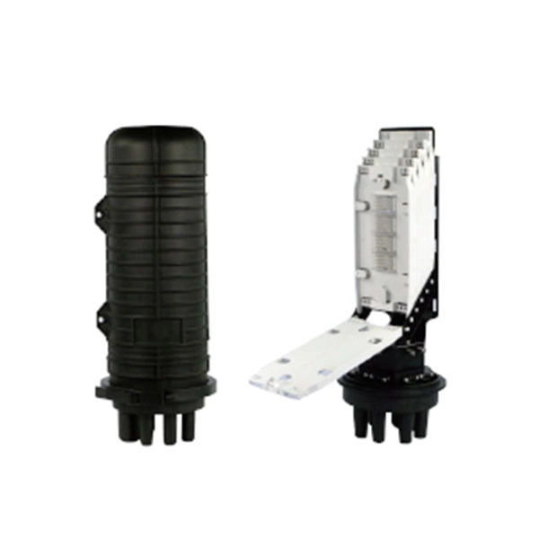
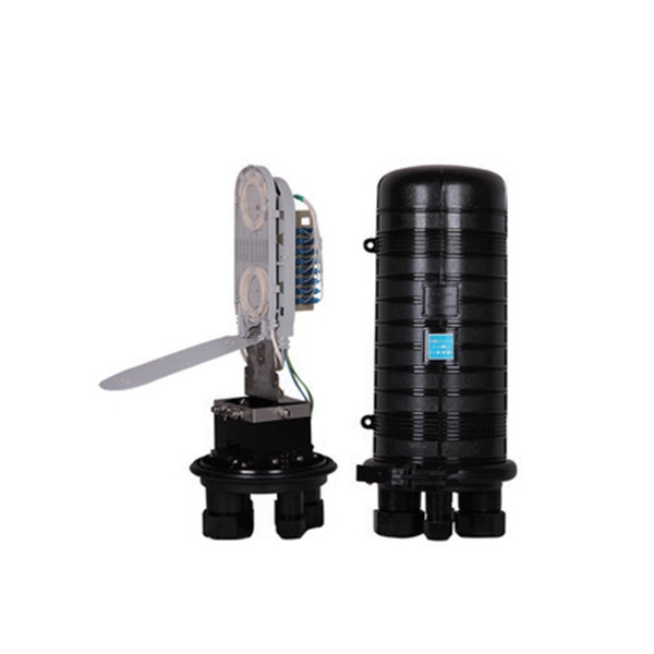
Fiber optic cable splicing techniques using heat shrink tubing
Carefully release each cable from splicer clamps. Slide shrink sleeve over exposed fiber and place in splicer's heating compartment; sleeve should cover each side roughly 3cm from joint. Consult the cable spec fication sheet for the cable you are installing. 1dB for fusion) and degrade over time in outdoor environments. A professional splice kit includes: Every splice starts with proper preparation: clean the work area, protect against wind, and. Single holed (preshrunk) ends eliminates improper fiber threading. Extended liner length prevents contact between the fiber and their backbone. Clear sleeve design permits easy centering. There are 7 procedures to perform in the splicing process; roughly in the following order: Procedures 2 and 3 will be performed twice; once for each of the two cables. Preparing to Use Heat Shrink Wrap: - Slide heat shrink wrap through one end of the fiber optic. A fiber optic heat shrink tube is used for reinforcing the splice connection.
[PDF Version]
-
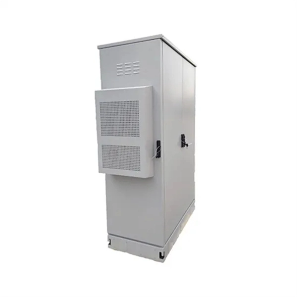
Edge computing using Greek network security equipment 1 6T
Edge computing is a model that brings computation and data storage closer to the. In edge computing, data may travel between different distributed nodes connected via the internet, and thus requires special encryption mechanisms independent of the cloud. This approach minimizes latency, reduces bandwidth consumption, and enhances real-time responsiveness for applications.DefinitionEdge computing involves running computer programs that deliver quick responses. Karim Arabi, during an IEEE DAC 2014 keynote and later at an MIT MTL Seminar in 2015, described e. In 2018, the world's data was expected to grow 61 percent to 175 by 2025. According to research firm Gartner, around 10 percent of enterprise-generated data is created and processed outside a traditional centralized. Edge application services reduce the volumes of data that must be moved, the consequent traffic, and the distance that data must travel. That provides lower latency and reduces transmission costs. • • • • •.
[PDF Version]