-

Estonian Electricity and Solar Wiring
As of the end of September, according to the data from Estonia's electricity system operator Elering, solar power plants accounted for 11. 2 per cent of Estonia's total consumption in 2023, and considering the large developments currently underway, renewable energy. Residents of Saaremaa already produce nearly half of the electricity they consume locally. However, the solar energy boom has led to a situation where many areas can no longer accommodate new micro-producers. TSO Elektrilevi's large-scale investments in Saaremaa and Hiiumaa will add additional. Estonia's electricity sector is interconnected with regional energy markets, particularly through connections with Finland and Latvia. The dataset presented in this study contains one year (2023) of photovoltaic (PV) generation and energy meter power flow data. Learn about the market conditions, opportunities, regulations, and business conditions in estonia, prepared by at U. Embassies worldwide by Commerce Department, State Department and other U. The Employer is Elering AS and contractors are Energex Energy Experts OÜ and EA Energianalyse a/s. Elering provided historical.
[PDF Version]
-
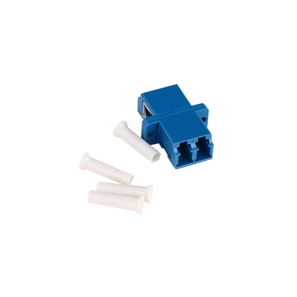
Fiber optic cable connection diagram with TX and RX switches
Fiber polarity is the direction that light signals travel from one end of a fiber optic cable (link) to the other. A link's transmit signal (Tx) must match its corresponding receiver (Rx) at the other end.
-
Home Fiber Optic Switch Connection Diagram
My network diagram. I came to the following requirement for my setup: In the end some of these didn't pan out as I will explain further down. I went with singlemode fiber with LC connectors in a G.657.
-
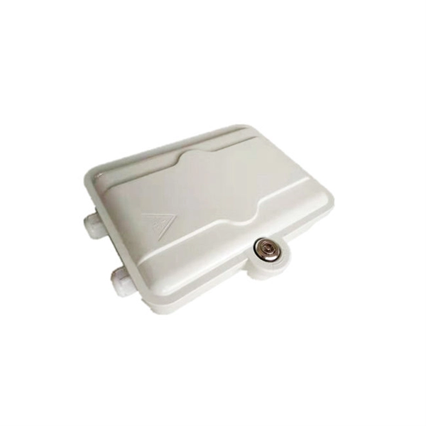
How to extend the wiring in a distribution box
Leave the receptacle wired, if wires are long enough to extend out to new position. Before you reach for a clumsy extension cord, consider a more permanent fix: extending electrical wire exactly where you need it. This creates a cleaner and safer setup. While the idea of extending electrical wiring can seem complex, it's based on a few core principles: shutting off the power. This specialized box provides a safe, contained space where the existing circuit wires can be physically joined with the new extension wires. more All My Favorite Tools: https://www. com/shop/everydayhomerepairsWAGO 221-413 or the 221-2401 make quick work of extending short wires.
-
Wiring of a Simple Distribution Box in a Factory
Practice good wiring: secure grounding, neat cable management, proper insulation, and correct wire gauge and breaker size. Include protection devices like breakers, fuses, and surge protectors—each circuit should have its own protection. Comply with standards: Follow NEC, IEC . Learn how to wire a distribution box step by step! This video shows real on-site footage of electrical installation, demonstrating safe and standardized wiring methods used by professionals. Single-phase distribution boards are mostly used in domestic house wirings such as houses offices, shops, etc. If it's done poorly, you risk short circuits, fire hazards, or system failure. Done right, it ensures safety, compliance, and long-lasting performance. To ensure safety, efficiency, and meet the increasing demand for usage, the electrical distribution system needs to meet the following. Connection method: Each switch takes a wire from the incoming point and connects it to the incoming end of the switch, or uses parallel connection to reduce the difficulty of wiring. This is important to properly install it.
[PDF Version]
-
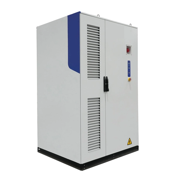
What issues should be considered when wiring the distribution box
Learn to identify & prevent power distribution cabinet installation problems like wiring errors, poor grounding, and safety risks to ensure building electrical system safety. It's always smarter to choose a box that's slightly larger than you think you'll need. A good box should have rust-proof coatings, especially for outdoor or humid. A cable distribution box is an electrical device used to collect, distribute, and protect electrical power. It is usually equipped with circuit breakers, fuses, terminal connectors, and other components. These can range from minor details to major safety defects. If your inspection report contains some of these, don't be alarmed; we are very picky, and many of the issues addressed here are common practice, if. Wiring Direction: Wiring between the main circuit breaker and each branch circuit breaker in the box generally goes on the left, and the wiring out of the distribution box generally goes on the right. Binding Requirements: The wires should be bound with plastic ties.
[PDF Version]
-
The eye diagram of the optical module is very poor
The key parameters used to judge whether an eye diagram is normal include eye height, eye width, jitter, and extinction ratio. For beginners, this might sound confusing—but don't worry. You will also get practical selection criteria, common failure modes, and a head-to-head decision matrix for choosing test setups. The eye diagram test is an indispensable methodology for evaluating the signal integrity and performance of high-speed digital communication systems, particularly in the domain of optical transceivers. The diagram is generated by overlaying multiple traces of a signal on an oscilloscope.
-
Electrical diagram of main distribution box
This AutoCAD DWG file provides a complete Electrical Single Line Diagram (SLD) of the MSB, along with a detailed panel layout, including circuit breakers, busbars, instruments, and feeders. Understanding the wiring diagram of the main electrical panel is crucial for anyone who wants to have a basic understanding of how electrical systems work. To understand how a breaker box works, it is helpful to. Power distribution panel is used for utilization of equipment. Power supply is received from LT panel and distributed to the outgoing feeders for utilization.