-
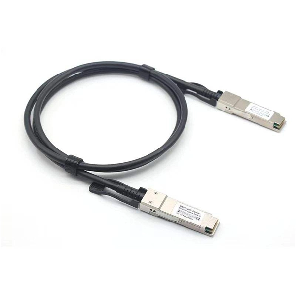
Selection Guide for 40G Tunable Optical Modules for Broadcast Transmission Grade
In this guide, we'll explore the different types of 40G optical transceivers, compare specifications like SR4 and LR4 optics, analyze compatibility with Cisco/Juniper platforms, and provide practical purchasing guidance for enterprises looking to deploy or upgrade their. In this guide, we'll explore the different types of 40G optical transceivers, compare specifications like SR4 and LR4 optics, analyze compatibility with Cisco/Juniper platforms, and provide practical purchasing guidance for enterprises looking to deploy or upgrade their. 40G QSFP+ modules are hot-swappable, quad-lane transceivers that deliver 40 Gbps by combining four 10. 3125 Gbps electrical/optical lanes — the form factor and lane mapping are defined in the QSFP+/SFF specifications. In this guide you will learn: The real differences between the main 40G QSFP+. The 40 gigabit transceiver, particularly the 40G QSFP+ module, plays a pivotal role in modern high-speed networks, especially data centers and enterprise backbones.
[PDF Version]
-
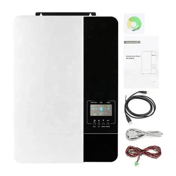
Selection Guide for OSFP and QSFP Optical Modules Used in Supercomputing Centers
This article compares OSFP and QSFP-DD in terms of physical dimensions, power and thermal characteristics, and compatibility, providing practical guidance for data center and network infrastructure planning. In the rapidly evolving landscape of high-performance computing and AI infrastructure, NVIDIA optical transceivers have emerged as critical components for enabling next-generation 800G network deployments. This guide gives you the complete picture. Our study of OSFP transceiver technology will begin with basic concepts and continue until we reach advanced technical. Today's mainstream 400G optical modules use three primary form factors: QSFP-DD, OSFP, and QSFP112. This article provides a comprehensive comparison of the three. In 2025, the optical transceiver market has shifted decisively. On the path to the 400G era, different form factors act as distinct engines, delivering.
[PDF Version]
-
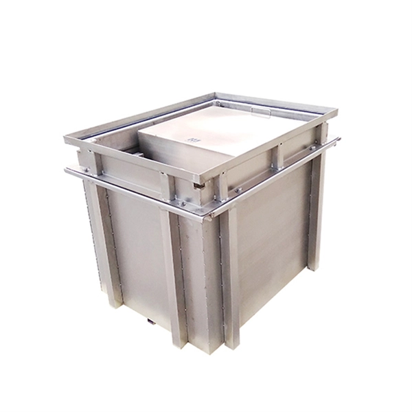
What are the components of an optical guide driver module
The optical module is usually composed of Transmitter Optical Subassembly (TOSA, containing a laser LD Chip), Receiver Optical Subassembly (ROSA, containing a photodetector PD Chip), a driving circuit, and an optical and electrical interface. Its schematic is shown in Figure 1. The internal structure of an optical module is complex but can be divided into several main parts. It is the core device for connecting communication equipment with optical fibers. Operating at the physical layer of the OSI model, optical modules are core devices in optical. As an important part of fiber-optic communication, an optical module is a photoelectric converter which converts electrical signals into optical signals and vice versa. Composition of Optical Modules The optical module, known as Optical Transceiver in. The optical module serves as a crucial component in optical fiber communication systems, operating at the physical layer, which is the lowest layer in the OSI model.
[PDF Version]
-
Syrian PAM4 optical transmitter
The system in this example contains the following elements: 1. 2 Pseudo-random Bit Stream (PRBS) block 2. 2 NRZ Pulse Generator (NRZ) 3. 1 CW Laser (CWL) 4. 3 1x2 Fork (FORK) 5. 2 Electrical Not Gate (N.
-
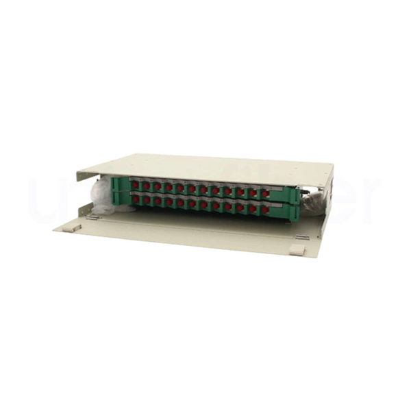
Understanding the wire numbers in the patch panel
Look at the back of the patch panel. Each port has a color-coded diagram showing exactly where each wire goes. In the United States, T568B is the standard for the vast majority of. The complete process for terminating cable runs at a patch panel, from mounting and cable management to punch-down, labeling, and testing every port. One commonly used wiring standard is T568B, which provides a standardized method for connecting Ethernet cables.