-
Campus Network Optical Line Terminal DML Overseas Warehouse
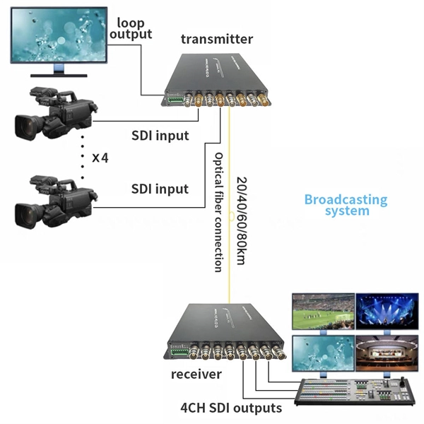
An optical line termination (OLT), also called an optical line terminal, is a device which serves as the service provider endpoint of a. It provides two main functions: 1. to perform conversion between the electrical signals used by the service provider's equipment and the signals used by the passive optical network.
-
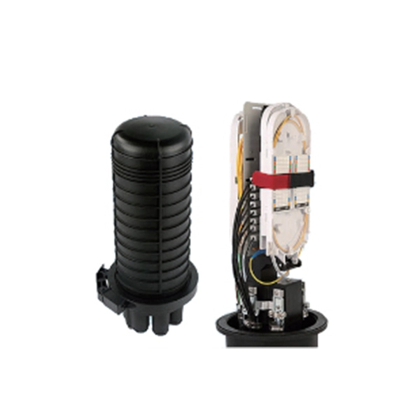
How many optical fibers can a fiber optic terminal box support at most
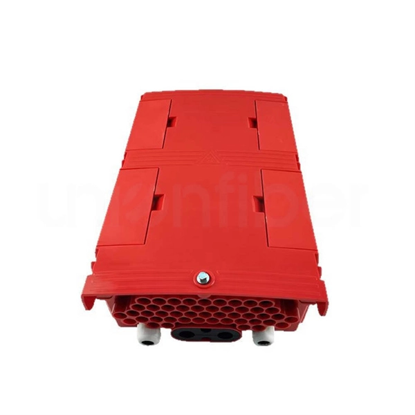
FTB max for mass deployment in residential units – terminates 168 fibers in a compact design. The HTB8048 Fiber Optic Terminal Box is a versatile, high-capacity termination solution for FTTx applications, offering secure fiber splicing, distribution, and cable management. The FTB product family offers modularity and ease of installation supporting multiple application options, significantly. This guide explains how to evaluate fiber termination box capacity correctly, including fiber count, port configuration, splitter accommodation, and future growth. Many buyers assume “capacity” simply means the number of adapter ports on the front panel (for example, 8 ports or 16 ports).
-
Each port of the optical splitter is bound to a user
The optical splitter divides optical power into n separate paths to end user. By dividing a single optical signal from a central Optical Line Terminal (OLT) into multiple outputs for Optical Network Terminals (ONTs) at users' homes, splitters eliminate the need for dedicated fibers to each residence—slashing infrastructure costs while scaling network reach. This guide. In a PON network, the splitter which is located between OLT and ONU functions as a traffic hub, adeptly managing the flow of optical signals. It operates like a sophisticated intersection, directing the singular flow of optical fibers to various users or devices, ensuring the efficient circulation. Centralized splitting means that the optical splitter between the optical line terminal (OLT) and the optical network unit (ONU) is parallel, and the basic form is “OLT→optical splitter→ONU”, in which the optical splitter ratio is usually 1:32. — (March 5, 2025)—The Fiber Broadband Association (FBA) announced the release of its latest resource in its Fiber 101 Series, “ Introduction to Passive Optical Network.
[PDF Version]
-
Eastern European GPON optical modules
The FTTH GPON market is analyzed, and market size insights and trends are provided by the component type, subscriber type, optical signalling format, technology, application, end user and countries a.
-
GPON optical module uplink
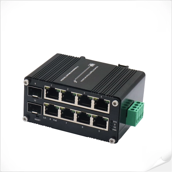
GPON is an alternative to Ethernet switching in campus networking. GPON replaces the traditional three-tier Ethernet design with a two-tier optic network which eliminates access and distribution Etherne.
-

Can GPON signals be connected to an optical switch
GPON is an alternative to Ethernet switching in campus networking. GPON replaces the traditional three-tier Ethernet design with a two-tier optic network which eliminates access and distribution Etherne.
-
Optical cable line faults are classified into three categories
According to the interruption of the optical fiber of the faulty cable, the fault types can be divided into three types: total interruption of the optical cable, interruption of part of the bundle tube, and interruption of part of the fiber in a single bundle tube. The optical cable is. This document is applicable to fiber optic patch cable products, which are categorized into two types: conventional fiber optic cables and multi-core fiber optic cables. Start with the simplest, fastest checks (visual inspection, cleaning, cable routing) and only move to instrumentation (power meter, VFL, OTDR) when those steps don't clear the fault. This saves time and prevents needless part swaps. These networks are the backbone of modern data transmission, offering incredible speeds and bandwidth.
-

Optical Cable Line Engineering Construction and Maintenance
These services include engineering and design, placement of aerial and underground optical fiber cable and coaxial construction, optical fiber cable splicing and testing, maintenance, installation and emergency restoration. Optical Fiber Cable Engineering Construction: A Comprehensive Operation Guide 1. Introduction Optical Fiber Cable engineering construction refers to the process of designing, planning, executing, and maintaining communication system infrastructure by deploying optical cables and associated. DeployCom is a premier provider of broadband design, engineering, construction and network installation for fiber optic cable services. Additionally, DeployCom provides project management, maintenance and disaster recovery services for broadband network projects. We approach each client's needs. The Fiber Optic Association, Inc. (FOA) was founded in 1995 to help develop the workforce to build the fiber optic networks to support a rapid expansion in communications and the Internet.
[PDF Version]
-
Temperature Measuring Optical Cable Fusion Splice Terminal
As heat sources in the fiber laser system, fusion points are among the most vulnerable parts in high power fiber lasers (HPFLs). A model is built to evaluate the heat induced by fusion splices quantitatively.
-
Method for calculating the intensity of the optical port of a beam splitter
Where intensity is in W/m² when power is in watts and area is in m². Rectangular spot: A =. T E3 + RE4, where T; R are the transmission and re ection coe cients for the beam splitter. Note that jT j2 is the transmitted intensity. The transformation matrix is then given by The elements of the beam splitter transformation matrix B are determined using the. The theory of the beam splitter (BS) in quantum optics is well developed and based on fairly simple mathematical and physical foundations. This theory has been developed for any type of BS and is based on the constancy of the reflection coefficients R (or the transmission coefficient T, where R + T. The Gaussian beam model provides a solution to the wave equation that describes the distribution of an electromagnetic field in free space or guiding structures like optical fibers. We use elementary laws of classical and quantum optics to obtain general relations among the magnitudes and phases of these probability amplitudes.
[PDF Version]