-
Normal transmit and receive power of optical module
Transmit power is typically good when it is in the 6 dB range between -1 and -7 dBm. This guide provides average transmit and receive power ranges for transceiver modules. The TX (transmit) and RX (receive) power levels significantly affect everything from signal strength to transmission distances and the overall optical power. For network engineers working with fiber optics (SFP, SFP+, QSFP), understanding TX (Transmit) and RX (Receive) signal strength is critical.
-
What s causing the optical module to have no light
Tip #5: How to deal with a “no light” issue? There are several reasons for “no light” issues: incompatible SFP module, incorrect connection, SFP module not powered on, or bad SFP. Incompatible SFP: Please check the compatibility of your optical transceiver with your. Tip #2: Why the LED of the switch slot does not light up after inserting the transceiver? It may cause by two reasons: compatibility issues and physical connection issues. If you have not inserted the SFP/SFP+/ XFP transceiver module into the switch slot correctly, it or link loss. The first thing. An optical module is a critical component in modern optical communication systems, directly affecting transmission stability, network reliability, and operational efficiency. However, during installation and daily operation, various issues may arise.
-
APM Optical Flow Module Debugging
Cut and resolder the MISOLVL jumper on the back of the board to switch the MISO pin to work on 3. If the sensor is mounted to a stabilized gimbal or mount, set FLOW_OPTIONS bit 1 to “1”. To know more about our new products, please visit www. com, we will serve you wh eed for GPS. This is critical to ensure the optical flow sensor does not interfere with APM is a open source flight control system, it is a multifunction system that can support quadrocopter, as well as aircrafts of fixed -wing, three-axis, 6-axis,8 –axis etc. APM flight control is a rather mature technique with formidable capabilities: it supports GPS designated cruise and automatic. Instead please use the PX4Flow sensor. The PX4FLOW is not yet supported in Plane or Rover. These are camera modules that use ground texture and visible features to determine aircraft ground velocity.
[PDF Version]
-
What are the components of an optical guide driver module
The optical module is usually composed of Transmitter Optical Subassembly (TOSA, containing a laser LD Chip), Receiver Optical Subassembly (ROSA, containing a photodetector PD Chip), a driving circuit, and an optical and electrical interface. Its schematic is shown in Figure 1. The internal structure of an optical module is complex but can be divided into several main parts. It is the core device for connecting communication equipment with optical fibers. Operating at the physical layer of the OSI model, optical modules are core devices in optical. As an important part of fiber-optic communication, an optical module is a photoelectric converter which converts electrical signals into optical signals and vice versa. Composition of Optical Modules The optical module, known as Optical Transceiver in. The optical module serves as a crucial component in optical fiber communication systems, operating at the physical layer, which is the lowest layer in the OSI model.
[PDF Version]
-
10 Gigabit Ethernet card optical module not connected to fiber optic cable
Troubleshooting SFP+ link issues in 10 GbE networks requires attention to module type, match of speed and wavelength, clean fiber connections, correct configuration, thermal management, and equipment compatibility. You can quickly resolve SFP+ Module connectivity issues by following a systematic optical transceivers troubleshooting process. Check for common connection problems, such as link failures or modules not recognized. Check compatibility between the optical module and switch Most switch brands have specific compatibility requirements. During network upgrades, many enterprise users encounter a common issue: after replacing 10G broadband lines or inserting 10G SFP+ optical modules, the switch still fails to operate at full 10G bandwidth or even fails to recognize the modules. We've listed the five most common ones. First of all, let's briefly recap what SFP and SFP+ stand for. SFPs – short for 'small form-factor pluggable' – are compact, hot-pluggable devices.
[PDF Version]
-
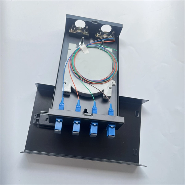
Does the optical splitter need an optical module and how is it connected
The optical transceiver module (like an SFP, SFP+, or XFP module) in the OLT is the laser source that generates the initial light signal. This high-power signal is transmitted down the single fiber. When it reaches the optical splitter, the signal is divided and sent. A fiber optic splitter is a passive optical component that divides a single incoming optical signal into two or more outgoing signals, or combines multiple incoming signals into one. Conversely, it can also combine multiple signals into one. It is a passive optical device with many input and output terminals, especially applicable to. An Optical Splitter (also known as a fiber optic splitter or beam splitter) is a passive optical power management device.
-
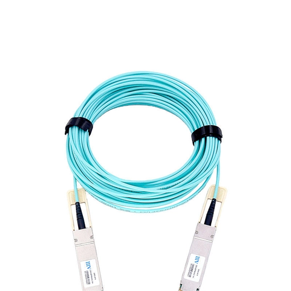
Is the R-port on the optical module for receiving or transmitting light
ROSA is the component inside the receiver side of the SFP port. The ROSA is responsible for receiving the optical signal transmitted by the TOSA of the opposite end's transceiver and converting it back to an electrical signal so that the communication equipment can understand it. Optical modules typically have an electrical interface on the side that connects to the inside of the system and an optical interface on the side that connects to the outside. The integrated optical transceiver module is the core device of optical communication, which completes the optical-electrical/electrical-optical conversion of optical signals. We'll cover everything from physical form factors to spectral characteristics, modulation formats. Ensures a proper connection between the optical module and the optical port of the device. It exists only on an SFP optical module.
[PDF Version]
-
When will Xiaomi s optical module be released
Xiaomi has recently made waves in the tech world by launching its groundbreaking modular optical system at MWC 2025. This innovative accessory is designed specifically for the Xiaomi 15, featuring a detachable 35mm lens that transforms mobile photography. Let's get into the details! The module is centered around a 100MP micro four-thirds sensor, paired with a 35mm f/1. The Chinese firm has yet to reveal whether it plans to bring the product to. Tech Advisor reports Xiaomi's modular camera lens concept is entering mass production after being showcased at MWC 2025.