-
Fiber optic cable does not support 1550
Multimode fiber is designed to operate at 850 and 1300 nm, while singlemode fiber is optimized for 1310 and 1550 nm. One of the major advantages of 1550 nm transmission is compatibility with Erbium-Doped Fiber Amplifiers (EDFA). All Singlemode fibers work very similarly in either wavelength—that is, you don't need to buy fiber based on wavelength, one fiber fits all. So, IF your cable assembly is built. This article delves into why 850, 1310, and 1550 nm are standard, what less-known regimes and tradeoffs exist, and how an OEM fiber-cable manufacturer can design and test with wavelength considerations built in. Consider the balance between attenuation and dispersion when designing your network for optimal performance.
-
How far apart should the cable tray be placed with its fixed support
Support spacing for cable trays must align with the manufacturer's instructions, as outlined in NEC 392. Generally, standard trays require supports every 6 to 10 feet, while heavy-duty, long-span trays can handle distances of up to 20 feet between supports. The NEC has a requirement for ladder-type cable trays. This is a description of how to select, install, and support these metal or plastic frames, on which electrical wires are installed. You should consider it as a series of instructions that make the buildings resistant to. When installing two cable trays in parallel at the same height, the distance between them should be no less than 0. But it's also important to minimize.
-
Cable tray support construction quotation
Get a quote through IndustryNet for Cable Trays. Send an RFQ / RFI / RFP to Featured and Preferred suppliers with the capabilities to meet your needs. Your inquiry will be sent out by email to all qualified vendors within one business day. no cost, hassle, or obligation!As the industry leader in cable tray, Eaton offers one of the widest ranges of B-Line series cable management solutions available in the market today. With unmatched quality and service, we offer a variety of styles, materials and finishes available to support virtually any commercial and. Learn how we've joined forces with Siemens Energy to fast-track data center construction and reduce deployment timelines by up to two years. We will figure all the cable tray components needed based on the total length you provide us. Simply give us the total linear foot of your. If specified NEMA class rating is not known, please answer the following 3a. They're also designed to maximize job-site efficiency.
[PDF Version]
-
Elevator cable tray support spacing
Support spacing for cable trays must align with the manufacturer's instructions, as outlined in NEC 392. Generally, standard trays require supports every 6 to 10 feet, while heavy-duty, long-span trays can handle distances of up to 20 feet between supports. Specifiers should be aware that some cable tray. Understanding cable tray spacing is key to meeting safety regulations and maintaining system performance. The spacing between trays, whether horizontal or vertical, depends on various factors like cable type, environment, and tray material. The Ladder Tray features light, rugged, tubular steel construction. 50 in the development and approval of the document at the time it was developed.
-
Are ladder racks used as support frames for cable trays
Ladder rack (also known as “ladder trays” or “cable ladders”) are one of the most common types of cable runway. As the name suggests, they're constructed of two side rails connected by rungs, creating an open structure for cable support and management. Whether suspended from the ceiling, wall-mounted, or supported by racks and cabinets, overhead cable management systems are flexible and scalable. They can easily be moved, reconfigured, or expanded as needed to meet changing requirements and evolving connectivity needs.
-
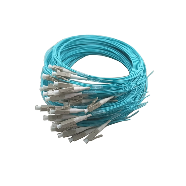
How many data rates can a single beam splitter support
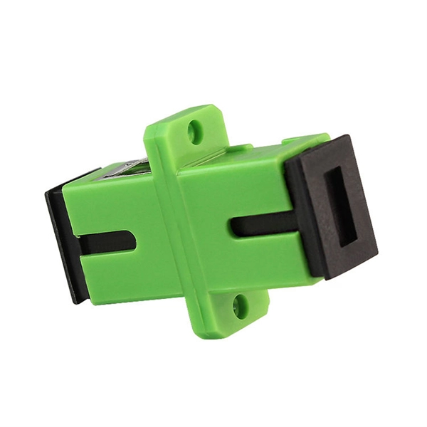
Fiber signals can be split through multiple configurations including 1×2, 1×4, 1×8, 1×16, 1×32, and up to 1×64 ratios. PLC splitters are high-quality with low failure rates that offer precise equal splitting for 1260 nm to 1650 nm operating wavelengths. Ratios are. These signals are divided by optical splitters and delivered to Optical Network Terminals (ONTs) at the customer premises. A key challenge is determining how many users a single OLT port can support, which is defined by the split ratio. According to the Broadband Forum, PLC splitters are essential for achieving scalable and cost-effective GPON and XGS-PON deployment in access networks. Network Scalability Enhancement: Single fiber serves multiple users, eliminating individual line requirements.
-
Troubleshooting Checklist for Fan Room Electrical Distribution Box
Check for any tripped breakers or blown fuses and replace them as necessary. Inspect and clean contacts to maintain good electrical conductivity. Internal Inspection Open. It is strongly recommended that the Air Movement and Control Association International Inc. (AMCA) Publication 202 “Troubleshooting” and AMCA Publication 410 “Recommended Safety Practices for Users and Installers of Industrial and Commercial Fans” be thoroughly read prior to any investigation. Power Distribution Unit (PDU) 1). LV Intrusive Switchboard Low-voltage intrusive switchboards regulate and distribute power in buildings and facilities. Be sure to have your badge scanned by a room monitor so a complete attendee. Check for any signs of damage, wear, or overheating in electrical panels, switchgear, transformers, and other equipment.
-
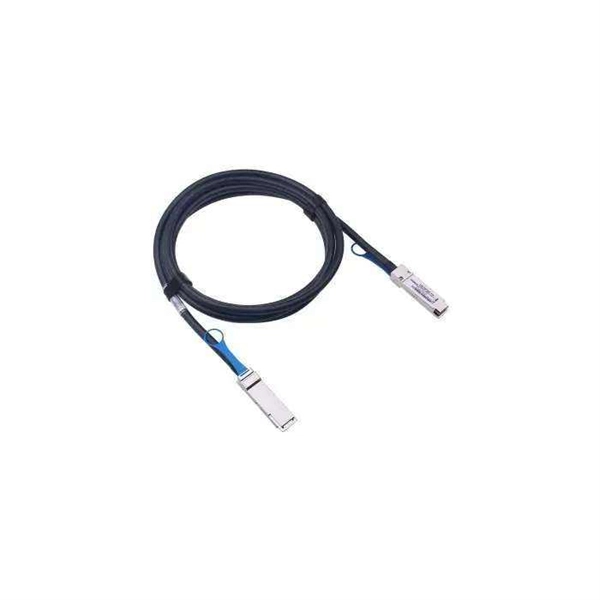
Steps for troubleshooting optical modules
Ensure module is fully seated, check optical power levels (Tx & Rx), replace suspect patch cord. Vendor incompatibility, outdated device firmware, incorrect module type for slot. Consult vendor compatibility list, upgrade device firmware, confirm module form-factor (SFP . Customers in the use of optical modules will more or less encounter a variety of failure problems, such as optical module model selection is correct, the use of jumper is correct and some common problems, customers have the ability to judge and have a clear solution, but for some of the use of. Based on typical issues encountered with optical modules in daily switch applications, this document summarizes basic troubleshooting steps for resolving common faults: 1. However, during installation and daily operation, various issues may arise. Therefore, understanding common optical module. The Ultimate Guide to Principles, Types, and Troubleshooting Optical Modules (also known as Optical Transceivers) are critical components in fiber optic communication systems. It is important to understand how to.
[PDF Version]