-
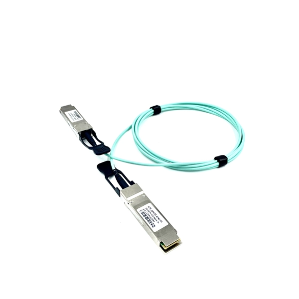
How to connect the 10 Gigabit Ethernet cable to the fiber-to-electrical port module
A special 10G Copper RJ-45 Transceiver (10G-SFP-T) is required to connect the SFP+ port to RJ45. It allows connecting a server/storage side Cat6/7 cable to an SFP+ port transceiver. An SFP module (or optical transceiver) converts electrical signals from network devices (switches, routers) into optical signals for fiber transmission and vice versa. 1G/10G SFP+: Standard for Gigabit and 10 Gigabit Ethernet. These transceiver modules are hot-swappable input/output (I/O) devices that plug into 100BASE, 1000BASE and 10GBASE ports (for SFP+), which connect the module port with the fiber-optic or copper network. 4ft (30m) * using Cat6a/Cat7 or above cable for 10G connection in various applications. In this video, we'll guide you through building a high-speed 10G LAN by connecting two fiber switches. Finally, check the transmit (TX) and receive (RX) paths to ensure that signals are aligned.
[PDF Version]
-
10 Gigabit Ethernet card optical module not connected to fiber optic cable
Troubleshooting SFP+ link issues in 10 GbE networks requires attention to module type, match of speed and wavelength, clean fiber connections, correct configuration, thermal management, and equipment compatibility. You can quickly resolve SFP+ Module connectivity issues by following a systematic optical transceivers troubleshooting process. Check for common connection problems, such as link failures or modules not recognized. Check compatibility between the optical module and switch Most switch brands have specific compatibility requirements. During network upgrades, many enterprise users encounter a common issue: after replacing 10G broadband lines or inserting 10G SFP+ optical modules, the switch still fails to operate at full 10G bandwidth or even fails to recognize the modules. We've listed the five most common ones. First of all, let's briefly recap what SFP and SFP+ stand for. SFPs – short for 'small form-factor pluggable' – are compact, hot-pluggable devices.
[PDF Version]
-
Function of DC Power Supply Remote Module
The MagnaDC power supply remote sense implements Smart Sense Detection, which shuts down and protects the product in the event that sense leads are disconnected while live or when the user leaves leads disconnected on start. Remote sense moves the feedback point external to the. The remote sense and trim functions of many DC DC converters seem easy enough to apply but, for optimum performance and minimum noise, some easily followed guidelines can prevent surprises in the customer's system. Remote sensing allows the customer to overcome voltage drops in the power lines by. Programmable DC power supplies are essential tools that can source power to a connected device. This article discusses – oscillations.
-
Increase the light output power of the optical module
An optical amplifier is a device which receives some input signal light and generates an output signal with higher optical power. Typically, inputs and outputs are laser beams (very rarely other types of light beams), either propagating as Gaussian beams in free space or in a fiber. At the receiver end, the optical signals are reconverted into electrical. In this guide, we will explain what optical signal strength is, how to check it on Cisco IOS using the command line, and how to troubleshoot common light level issues. Assume the. This application note gives a short introduction to optical modules and the need of an optimized power tree in them and then concentrates on the use cases and benefits of four-switch and inverting buck-boost converters inside optical modules.
-
The higher the optical power of the optical module the better
The optical power budget represents the maximum allowable signal loss in a fiber-optic link. It is calculated by subtracting the RX sensitivity from the TX power. The transmitted optical power of the optical module is an important parameter that affect the transmission distance of the optical module. The stronger the. In the world of enterprise and data center networking, Small Form-factor Pluggable (SFP) modules are the quiet workhorses that connect routers, switches, and optical fiber links.
-

Optical module connected to lc
Most SFP fiber optic modules use LC connectors, while SC connectors are mainly found in legacy networks and MPO/MTP connectors are used for high-density cabling rather than directly on standard SFP modules. You may find LC connector has a strong family which includes but not limited to LC optical fiber connectors, LC fiber patch cables, LC fiber. This guide provides a fully updated and industry-ready overview of LC fiber optics, explaining the origin and design of LC connectors, their key features, and the complete ecosystem of LC-based products used in modern networking. Components and Structure There are two main components — the SFP transceiver and the LC connector in the SFP LC connector. The outer parts of the connector are precision plastic parts, including a push-pull plug-in clamping mechanism. Suitable for indoor applications in telecommunications and data network.
[PDF Version]
-
How are the pins of the 2609B optical receiver module
With 900um-buffered single-mode fiber, without fiber connector. Internal current gain: 6 dB (typ. The 2609B is a packaged impedance-matched photodiode module with internal gain designed for use in optical broadband receivers in. The 2609B is a packaged impedance-matched photodiode module with internal gain designed for use in optical broadband receivers in fiber-optic networks. These are absolute stress ratings only. Functional operation of the device is not implied at these or any other conditions in excess of those given in the operational sections of the data sheet. Exposure to. no available.
-
Steps for replacing the CPU module of a relay protection device
Learn the essential steps for safely removing and reinstalling a PLC CPU module to prevent equipment damage, data loss, or safety hazards. Always consult the manufacturer's documentation for model-specific instructions. Incorrect wiring may result. 1. 1 INTRODUCTION TO THE UR The GE Universal Relay (UR) series is a new generation of digital, modular, and multifunction equipment that is easily incorporated into automation systems, at both the station and enterprise levels. The application software. Manual intended for personnel responsible for installing, commissioning and using VIP protection 400. The following steps outline best practices, but always consult the. This handbook covers the code of practice in protection circuitry including standard lead and device numbers, mode of connections at terminal strips, colour codes in multicore cables, dos and donts in execution.
[PDF Version]
-
Optical Module Base Design
Optical module usually consists of a transmitter assembly (TOSA, containing a laser LD chip), a receiver assembly (ROSA, containing a photodetector PD chip), a driver circuit, an optoelectronic interface, a heat sink (some models), a housing, a pull ring and so on. Integrated circuits and reference designs help you create a smaller and faster optical module design used in high-bandwidth data communication applications. Whether you are creating a 100-Gbps or 400-Gbps, small form-factor pluggable (SFP) module, SFP+ transceiver, XFP module, CFP, X2/XENPAK module. Designing and producing these complex PCBs presents formidable challenges, requiring a convergence of disciplines—from high-frequency signal integrity and advanced thermal management to micron-level mechanical precision. These three laser diodes are described in more detail. contact us product page Copyright © 2024 MVSLINK. Critical Metrics: Signal integrity (insertion loss, return loss) and thermal management are the two.
[PDF Version]
-
Function of optical module IC
The optical module serves as a crucial component in optical fiber communication systems, operating at the physical layer, which is the lowest layer in the OSI model. Its primary function is to achieve optoelectronic conversion by converting electrical signals into optical signals and vice versa.
-
How to connect an optical port module to a router
Plug the SFP module into the router's SFP port for fibre optic connectivity. No additional settings need to be made. The assignment of any port on the built-in managed switch of the router can be changed according to the user's. This guide provides a clear, step-by-step explanation of how to install an SFP module correctly, based on real-world deployment practices. SFP Transceiver Module – Choose the appropriate module based on your network requirements (e., 1G, 10G. To plug in a fiber SFP (Small Form-factor Pluggable) module, follow these steps: 1. 1G/10G SFP+: Standard for Gigabit and 10 Gigabit Ethernet. To avoid static discharge damage, use an anti-static wrist strap. Installation Tips for. The SFP+ port is a high-speed optical-to-optical signal conversion port, mainly used for 10G Ethernet and Fiber Channel network applications.