-
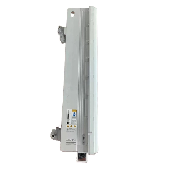
10 Gigabit Ethernet card optical module not connected to fiber optic cable
Troubleshooting SFP+ link issues in 10 GbE networks requires attention to module type, match of speed and wavelength, clean fiber connections, correct configuration, thermal management, and equipment compatibility. You can quickly resolve SFP+ Module connectivity issues by following a systematic optical transceivers troubleshooting process. Check for common connection problems, such as link failures or modules not recognized. Check compatibility between the optical module and switch Most switch brands have specific compatibility requirements. During network upgrades, many enterprise users encounter a common issue: after replacing 10G broadband lines or inserting 10G SFP+ optical modules, the switch still fails to operate at full 10G bandwidth or even fails to recognize the modules. We've listed the five most common ones. First of all, let's briefly recap what SFP and SFP+ stand for. SFPs – short for 'small form-factor pluggable' – are compact, hot-pluggable devices.
[PDF Version]
-
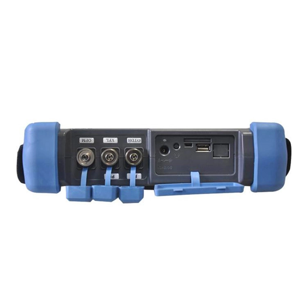
How to connect the 10 Gigabit Ethernet cable to the fiber-to-electrical port module
A special 10G Copper RJ-45 Transceiver (10G-SFP-T) is required to connect the SFP+ port to RJ45. It allows connecting a server/storage side Cat6/7 cable to an SFP+ port transceiver. An SFP module (or optical transceiver) converts electrical signals from network devices (switches, routers) into optical signals for fiber transmission and vice versa. 1G/10G SFP+: Standard for Gigabit and 10 Gigabit Ethernet. These transceiver modules are hot-swappable input/output (I/O) devices that plug into 100BASE, 1000BASE and 10GBASE ports (for SFP+), which connect the module port with the fiber-optic or copper network. 4ft (30m) * using Cat6a/Cat7 or above cable for 10G connection in various applications. In this video, we'll guide you through building a high-speed 10G LAN by connecting two fiber switches. Finally, check the transmit (TX) and receive (RX) paths to ensure that signals are aligned.
[PDF Version]
-
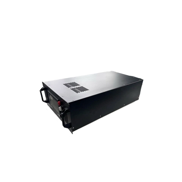
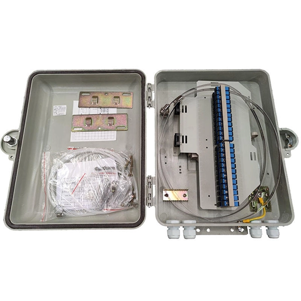
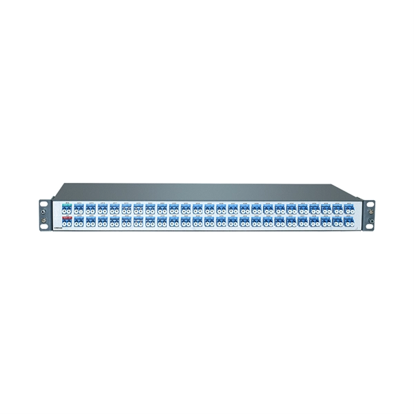
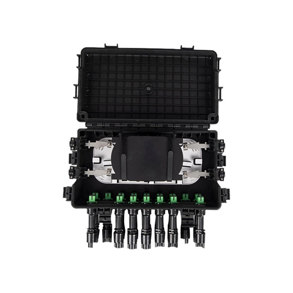
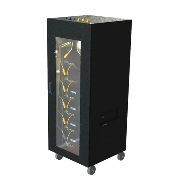
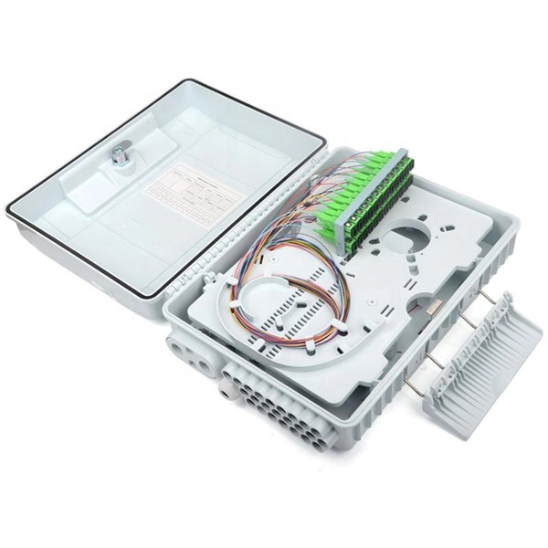
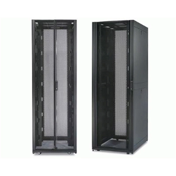
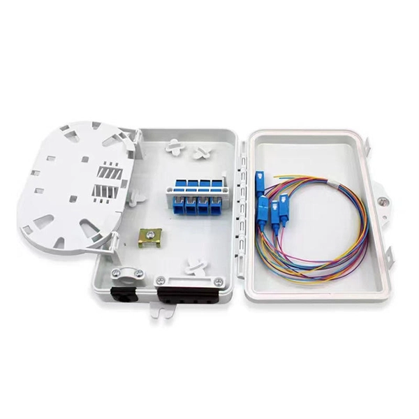
What is a fiber optic cable management rack also called
Also known as fiber optic enclosures or fiber entrance cabinets, these enclosures act as hubs where cables can be spliced, organized and routed through areas inside or outside a building. This article provides a clear technical view of cable management racks, their structures, and how to select the right solution for modern networks. It houses and protects fibre terminations, allowing you to manage high volumes of optical connections in a secure, scalable format. The Rack Mounted Optical Cable Terminal Box is a metal enclosure used for fiber cable. Fiber enclosures come in two primary types: wall mount and rack mount. On the other hand, rack-mount fiber enclosures are employed between or within. What Is a Fiber Patch Panel? A fiber patch panel is a mounted enclosure—either rack-mounted or wall-mounted—used to terminate, manage, and interconnect multiple fiber optic cables. Given its immense significance, it is essential for.
[PDF Version]
-
Working principle of 10 Gigabit fiber optic patch cord
The functioning of a fiber optic patch cord relies on its construction. It consists of a core with a high refractive index, enveloped by a coating featuring a lower refractive index. This assembly is fortified using aramid yarns and encased within a protective jacket. These cables, also known as fiber optic patch cables or jumpers, are designed to transmit information as pulses of light, offering unparalleled speed, bandwidth, and immunity to electromagnetic interference compared to traditional copper cables. As network demands continue to explode, selecting the. Key factors to consider in the design of 10 Gigabit Ethernet networks are: The network topology, including operating distances, splice losses and numbers of connectors (i. Fiber optic patch cables are found almost everywhere; cable television networks (CATV), data centers, computer networks, and telephone networks.
[PDF Version]
-
The bottom plate of the trough-type cable tray has holes
A perforated cable tray—also called a ventilated trough tray —features a solid bottom with regularly spaced ventilation holes and continuous side rails. Some versions have small holes in the bottom. It is good for routing control cables and communication cables. From a structural. The ladder-type cable tray is designed with two long side rails that are connected by evenly spaced rungs, resembling a ladder.
-
Typical installation height of indoor cable trays
The 2026 NEC introduced an important update: cable trays must have at least 12 inches of clear vertical space above them to allow for installation and maintenance access. Article Summary: A compliant cable tray installation requires a thorough understanding of NEC Article 392, proper structural support, and precise installation techniques. This guide covers the critical steps, from selecting the right electrical cable tray and performing accurate cable fill. We recognize the need for a complete cable tray reference source for electrical engineers and designers. Trays and fittings should be stacked by their physical dimensions (width) and type. us-trations without notice. All illustrations, descriptions and technical information included in this document are provided as indications and can cable trays are equivalent. Wire Mesh Cable Trays A job site, field adaptable support system primarily for.
[PDF Version]
-
Cable tray dip coating process
Steel trays get dipped in very hot molten zinc (around 450°C). The zinc bonds tightly to the steel, creating a thick, tough layer. Process: Degreasing → Pickling → Rinsing → Fluxing → Drying → Hot-dip galvanizing → Cooling → Passivation (optional) → Inspection. Hot-dip galvanizing is a process that enhances the durability of cable trays by creating a protective zinc coating, safeguarding them from corrosion. It is cost-effective, protects against a wide variety of environmental chemicals, and is self-healing if an area becomes unprotected through cuts or scratches. Steel is coated with zinc through electrolysis by dipping steel into a bath of. Legrand's offer of global solutions for wiremesh cable trays (and accessories) is one of the most complete on the market. It offers true freedom by allowing multiple configurations in a wide choice of finishes for optimal integration into any environment.
[PDF Version]
-
Fiber optic cable connected to router then connected to switch
If using a network switch with SFP ports, insert the fiber optic transceiver into the SFP port and connect the fiber optic cable to the transceiver. Connect the other end of the Ethernet cable to your network device, such as a computer, router, or. Fiber Optic Transceiver: Often used with media converters or network switches, these devices convert electrical signals to optical signals and vice versa. Patch Panel. As we speak I just have optic fibre (Community Fibre) connected to my Huawei modem / Linksys Velop which will be connected to a new POE switch (need to identify the best model to be compatible with my optic fibre extension project). Network topology refers to the way in which the links and nodes of a network are arranged in relation to each other. Use a standard Ethernet cable (Cat5e/Cat6) to.
[PDF Version]
-
Benin Optical Cable Blowing Machine
A cable blowing machine (also known as a fiber blowing machine) is a machine designed to fit cables into telecommunication ducts and with the use of compressed air or water.
-
Underground Depth of Optical Cable
Fiber optic cables are typically buried between 12 and 36 inches (30–90 cm), depending on installation environment, soil conditions, and load requirements. In high-load areas such as roads or backbone routes, burial depth can reach 48 inches (120 cm) or more. With international fiber networks predicted to grow to over 1. 8 million km in scope by 2025 (per TeleGeography), burying these cords of light comes with the benefits of avoiding cable damage, decreasing downtime, and extending their operational lifetime. For broader context on underground. Underground cables are pulled in conduit that is buried underground, usually 1-1. 2 meters (3-4 feet) deep to reduce the likelihood of accidentally being dug up. In extreme cold climates, cables may need to be buried at greater depths where there temperatures are colder and frost penetrates to. Estimate minimum burial depth (cover) for underground electrical, fiber, and low-voltage cable runs using a practical, code-aware ruleset. Always consult local utility regulations and obtain necessary permits before excavation.
[PDF Version]
-
Manufacturing of Trapezoidal Cable Tray Elbows
Professional Cable Tray Elbow Making | Metal Fabrication Tutorial Learn how to make cable tray elbows professionally with step-by-step guidance. Whether you are a DIY enthusiast. Search by Cooperative Patent Classifications (CPCs): These are commonly used to represent ideas in place of keywords, and can also be entered in a search term box. If you're searching for seat belts, you could also search for B60R22/00 to retrieve documents that mention safety belts or body. Cable trays and fittings from Selco Manufacturing offer distinct advantages for various applications. The following are some key benefits and considerations to guide your selection process. There are several essential benefits of using cable trays from Selco Manufacturing, including: Better. This manual is designed to guide workers through the detailed production process of ladder cable trays, including the manufacture of horizontal elbows, tees, crosses, reducing bends, and vertical bends, with emphasis on precision, safety, and quality control.
[PDF Version]
-
How to install the cable tray beam bend
The fittings can fastened to the cable tray rail either with double clamps of type DOP A2 or with truss-head bolts of type FRS and combination nuts. The exceptions to this are vertical bends, adjustable bend elements and fittings with a side height of 35 mm. These fittings can only be screwed on. Beam bracket PK1 is attached to the lower flange of an I beam. These guidelines are not intended to cover all details or variations in cable ladder and cable tray. en completely installed, without damage either to conductors or structural system use maintain spacing or to keep cables in place when the tray is ect the minimum bend ra-dius for cables as they exit the bottom of the cable tray. A rung spacing of 6 to 9 inches (150 to 230 mm) is preferable when. Hubbell's NEXTFRAME® Ladder Tray is the effective and widely used cable runway that supports and delivers bundles of cable between cabinets, racks, and closets, along walls, and suspended from ceilings. Cable ladder systems and cable tray systems shall be manufactured in accordance with BS EN 61537, channel support.
[PDF Version]