-
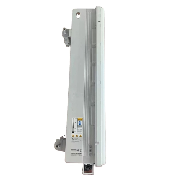
10 Gigabit Ethernet card optical module not connected to fiber optic cable
Troubleshooting SFP+ link issues in 10 GbE networks requires attention to module type, match of speed and wavelength, clean fiber connections, correct configuration, thermal management, and equipment compatibility. You can quickly resolve SFP+ Module connectivity issues by following a systematic optical transceivers troubleshooting process. Check for common connection problems, such as link failures or modules not recognized. Check compatibility between the optical module and switch Most switch brands have specific compatibility requirements. During network upgrades, many enterprise users encounter a common issue: after replacing 10G broadband lines or inserting 10G SFP+ optical modules, the switch still fails to operate at full 10G bandwidth or even fails to recognize the modules. We've listed the five most common ones. First of all, let's briefly recap what SFP and SFP+ stand for. SFPs – short for 'small form-factor pluggable' – are compact, hot-pluggable devices.
[PDF Version]
-

Switches are all 10 Gigabit optical
To implement different 10GbE physical layer standards, many interfaces consist of a standard socket into which different physical (PHY) layer modules may be plugged. PHY modules are not specified in an official standards body but by (MSAs) that can be negotiated more quickly. Relevant MSAs for 10GbE include (and related X2 and XPAK), and. When choosing a PHY.
-
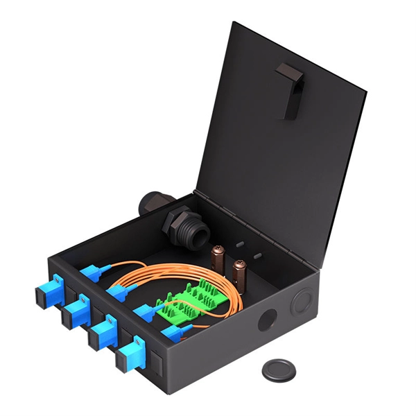
The function of a 10 Gigabit optical splitter
By dividing a single optical signal from a central Optical Line Terminal (OLT) into multiple outputs for Optical Network Terminals (ONTs) at users' homes, splitters eliminate the need for dedicated fibers to each residence—slashing infrastructure costs while scaling network reach. An Optical Splitter, also known as a beam splitter, is a passive optical device that divides a single input optical signal into two or more output signals. Conversely, it can also combine multiple signals into one. Optical splitter. Where splitters are placed in the network can make significant impacts on fiber counts, network cost and deployment time and operational steps, such as customer onboarding and maintenance. One important note is that splitting architectures should be seen as tools that can be mixed and matched to. The trick is how that single signal gets divided. That's where splitters come in.
[PDF Version]
-
How to connect the 10 Gigabit Ethernet cable to the fiber-to-electrical port module
A special 10G Copper RJ-45 Transceiver (10G-SFP-T) is required to connect the SFP+ port to RJ45. It allows connecting a server/storage side Cat6/7 cable to an SFP+ port transceiver. An SFP module (or optical transceiver) converts electrical signals from network devices (switches, routers) into optical signals for fiber transmission and vice versa. 1G/10G SFP+: Standard for Gigabit and 10 Gigabit Ethernet. These transceiver modules are hot-swappable input/output (I/O) devices that plug into 100BASE, 1000BASE and 10GBASE ports (for SFP+), which connect the module port with the fiber-optic or copper network. 4ft (30m) * using Cat6a/Cat7 or above cable for 10G connection in various applications. In this video, we'll guide you through building a high-speed 10G LAN by connecting two fiber switches. Finally, check the transmit (TX) and receive (RX) paths to ensure that signals are aligned.
[PDF Version]
-
Huawei optical modules are compatible with 10 Gigabit and 1 Gigabit speeds
31 Gbps data rate and such applications as 10G Ethernet (10. SFP+ Double Fiber optical transceiver is multi-purpose module used in number of different places of today's networking. Huawei is not liable for any problem caused by the use of non-certified optical or copper. Huawei compatible SFP+10GE-LH10-SM1310 (02311MUU) is SFP+ (Small Form factor Pluggable) Transceiver, operating over Double Fiber Single-Mode Fiber (SMF) optical cable. In today's fiercely competitive environment, people's demands for quality are increasing. The primary difference is that SFP+ is an updated version of SFP but supports higher speeds up to 10Gbps. If the SFP-10G-ER-1310 is connected. Can 1G SFP optics work with 10Gb SFP+ ports on a 10Gb switch, or vice versa? This comprehensive guide reveals the intricacies of SFP and SFP+ compatibility and provides useful solutions for network switch users.
[PDF Version]
-
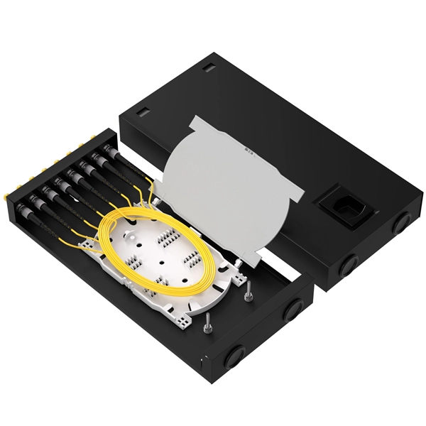
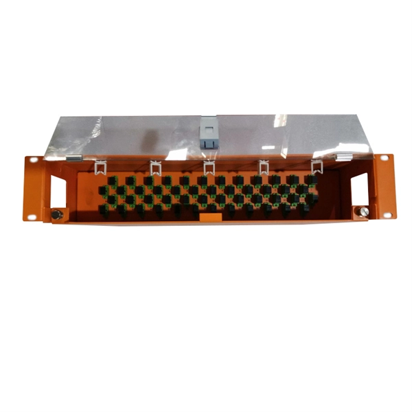
Working principle of 10 Gigabit fiber optic patch cord
The functioning of a fiber optic patch cord relies on its construction. It consists of a core with a high refractive index, enveloped by a coating featuring a lower refractive index. This assembly is fortified using aramid yarns and encased within a protective jacket. These cables, also known as fiber optic patch cables or jumpers, are designed to transmit information as pulses of light, offering unparalleled speed, bandwidth, and immunity to electromagnetic interference compared to traditional copper cables. As network demands continue to explode, selecting the. Key factors to consider in the design of 10 Gigabit Ethernet networks are: The network topology, including operating distances, splice losses and numbers of connectors (i. Fiber optic patch cables are found almost everywhere; cable television networks (CATV), data centers, computer networks, and telephone networks.
[PDF Version]
-
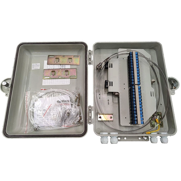
Minimum wire diameter between distribution boxes
When installing insulated conductors of 4 AWG or larger, the minimum dimensions of pull or junction boxes installed in a raceway or cable run must comply with 314. A conduit body is a removable-cover section of a conduit system that provides access at junctions or termination points. Article 314 applies to: These. Professional electrical wire sizing tool based on National Electrical Code (NEC) standards. Calculate proper wire gauge, voltage drop, and ampacity for safe electrical installations. Typically available in depths ranging from 1-1/2 inches to 2-1/8 inches, their square shape provides ample internal volume for making multiple wire connections and. This standard describes the design of individual electrical power circuits for illumination, signal, and ITS equipment, powered from WSDOT electrical service cabinets, and the associated features required in the service cabinet to support these circuits. Minimum box length must be at least 8 × the largest conductor diameter.
[PDF Version]
-
The ground wire can be seen in the distribution box
Open the distribution box and find the position marked with the grounding plate or PE letter. Connect the power ground wire Connect the ground wire in the power supply directly to the. The correct connection method of Distribution box grounding wire mainly includes the following steps: 1. This position is the connection point of the grounding wire in the. How to make proper & safe electrical ground wiring connections in the box: This article describes options for connecting a metal electrical box to the grounding conductor & connecting the grounding conductor to a fixture such as a ceiling light or ceiling fan. Understanding its role is essential for locating it safely. Preparation: First, you need to prepare some necessary tools, including grounding wire, grounding rod, voltmeter, insulating gloves and insulating tools. Make sure all tools are intact to prevent accidents during the grounding. On the US market, a 5. 26 mm 2 (10 AWG) ground wire must be used, and in all other markets a 6 mm 2 must be used.
[PDF Version]
-

The pigtail has no steel wire
What kind of wire do you use for pigtails? You can make a pigtail with either thermoplastic high-heat-resistant nylon-coated (THHN) wire or non-metallic (NM) cable, often referred to as “Romex. ” Each pigtail requires a neutral wire, a ground wire, and a live wire. This gap in awareness matters because these connections ensure energy flows safely, even when devices malfunction. Pigtails serve. An electrical pigtail is a short piece of wire used to connect an electrical device, such as a switch or receptacle, to the main circuit conductors within a junction box.
-
Principle of Grounding Wire in Home Electrical Distribution Box
The ground wire working principle is based on providing a low-resistance path for fault current to flow safely into the earth. Electricity always follows the path of least resistance. Grounding ensures that fault current prefers the ground path instead of passing through the human. Whether you're a seasoned pro or just starting out, this comprehensive guide will give you practical insights into proper grounding techniques, with a special focus on how selecting quality materials from a reliable building material supplier impacts your entire system's safety and longevity. Installed correctly, grounding wire can prevent electrical shocks or fires at homes or in offices. It. Publish Time: 03/10 2025 Author: Site Editor Visit: 969 The correct connection method of Distribution box grounding wire mainly includes the following steps: 1. The ground wire. Grounding means connecting to the Earth or extending the ground connection to other things in your home, such as the metal frames and components of electrical equipment, wiring, appliances, light fixtures and receptacles — even if they're far away from the actual ground. Establishing a connection.
[PDF Version]
-

How to learn how to wire a distribution box
In this video, we'll walk you through the process of wiring a home distribution box with a detailed connection diagram. more Welcome to our. Learn how to wire a distribution box step by step! This video shows real on-site footage of electrical installation, demonstrating safe and standardized wiring methods used by professionals. Covers wiring, placement, standards, and expert tips for a compliant setup.
-
What are the required specifications for the ground wire of the distribution box
26 mm 2 (10 AWG) ground wire must be used, and in all other markets a 6 mm 2 must be used. On the US market, a 5. The National Electrical Code (NEC) provides clear guidelines for ground wire sizing through Table 250. 122, but understanding how to apply these requirements correctly can make the difference between a safe installation and a costly code violation. Proper grounding conductor sizing is critical for. Correct grounding of services depends upon understanding the definition and role of the grounded conductor. Each DISTRIBUTION BOX and controller must be grounded. Today, we're diving deep into the world of distribution box grounding, breaking down the standards.