-
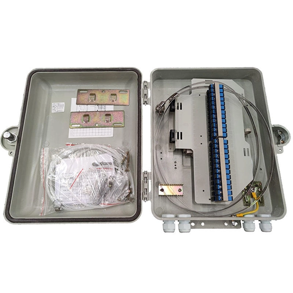
The function of a 10 Gigabit optical splitter
By dividing a single optical signal from a central Optical Line Terminal (OLT) into multiple outputs for Optical Network Terminals (ONTs) at users' homes, splitters eliminate the need for dedicated fibers to each residence—slashing infrastructure costs while scaling network reach. An Optical Splitter, also known as a beam splitter, is a passive optical device that divides a single input optical signal into two or more output signals. Conversely, it can also combine multiple signals into one. Optical splitter. Where splitters are placed in the network can make significant impacts on fiber counts, network cost and deployment time and operational steps, such as customer onboarding and maintenance. One important note is that splitting architectures should be seen as tools that can be mixed and matched to. The trick is how that single signal gets divided. That's where splitters come in.
[PDF Version]
-
How to connect the 10 Gigabit Ethernet cable to the fiber-to-electrical port module
A special 10G Copper RJ-45 Transceiver (10G-SFP-T) is required to connect the SFP+ port to RJ45. It allows connecting a server/storage side Cat6/7 cable to an SFP+ port transceiver. An SFP module (or optical transceiver) converts electrical signals from network devices (switches, routers) into optical signals for fiber transmission and vice versa. 1G/10G SFP+: Standard for Gigabit and 10 Gigabit Ethernet. These transceiver modules are hot-swappable input/output (I/O) devices that plug into 100BASE, 1000BASE and 10GBASE ports (for SFP+), which connect the module port with the fiber-optic or copper network. 4ft (30m) * using Cat6a/Cat7 or above cable for 10G connection in various applications. In this video, we'll guide you through building a high-speed 10G LAN by connecting two fiber switches. Finally, check the transmit (TX) and receive (RX) paths to ensure that signals are aligned.
[PDF Version]
-
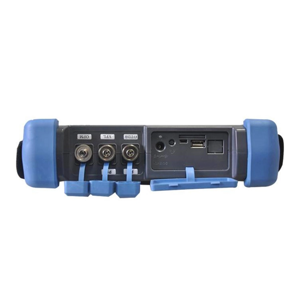
10 Gigabit Ethernet card optical module not connected to fiber optic cable
Troubleshooting SFP+ link issues in 10 GbE networks requires attention to module type, match of speed and wavelength, clean fiber connections, correct configuration, thermal management, and equipment compatibility. You can quickly resolve SFP+ Module connectivity issues by following a systematic optical transceivers troubleshooting process. Check for common connection problems, such as link failures or modules not recognized. Check compatibility between the optical module and switch Most switch brands have specific compatibility requirements. During network upgrades, many enterprise users encounter a common issue: after replacing 10G broadband lines or inserting 10G SFP+ optical modules, the switch still fails to operate at full 10G bandwidth or even fails to recognize the modules. We've listed the five most common ones. First of all, let's briefly recap what SFP and SFP+ stand for. SFPs – short for 'small form-factor pluggable' – are compact, hot-pluggable devices.
[PDF Version]
-

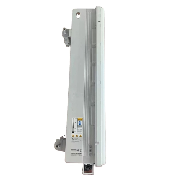
Switches are all 10 Gigabit optical
To implement different 10GbE physical layer standards, many interfaces consist of a standard socket into which different physical (PHY) layer modules may be plugged. PHY modules are not specified in an official standards body but by (MSAs) that can be negotiated more quickly. Relevant MSAs for 10GbE include (and related X2 and XPAK), and. When choosing a PHY.
-
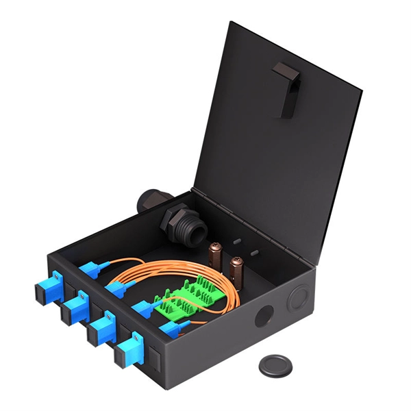
Working principle of 10 Gigabit fiber optic patch cord
The functioning of a fiber optic patch cord relies on its construction. It consists of a core with a high refractive index, enveloped by a coating featuring a lower refractive index. This assembly is fortified using aramid yarns and encased within a protective jacket. These cables, also known as fiber optic patch cables or jumpers, are designed to transmit information as pulses of light, offering unparalleled speed, bandwidth, and immunity to electromagnetic interference compared to traditional copper cables. As network demands continue to explode, selecting the. Key factors to consider in the design of 10 Gigabit Ethernet networks are: The network topology, including operating distances, splice losses and numbers of connectors (i. Fiber optic patch cables are found almost everywhere; cable television networks (CATV), data centers, computer networks, and telephone networks.
[PDF Version]
-
New Solution for Outdoor Energy Storage Cabinets in Brazil
China's Risen Energy is deploying containerized BESS units across Brazil's northeast—enough to power 70,000 homes during blackouts. Local startups are aggregating rooftop solar + storage into Brazil's first VPP network, with 200MW planned by Q3 2026. In 2025 alone, projects like the Ilha Solteira hydropower-solar hybrid and MTR Solar's 1GWh mega-deal are rewriting the rules of clean energy storage. But what's fueling. Aluminium-ion batteries (AIB) are a class of in which ions serve as. This means that insertion of one Al is equivalent to three Li ions. Thus, since the ionic radii of Al (0. The exhibition gathered over 300 global industry players, local utilities, and commercial clients. Brazil's distributed solar capacity surged to 40GW (2025) from <1GW (2018), making it the nation's fastest-growing energy source (67. A 2025 grid fee policy spurred pre-2023 installations, but grid curtailment (21% in NE Brazil) and new costs challenge growth. Rodrigo Sauaia, executive president of Absolar, and Barbara Rubim, CEO of Bright Strategies.
[PDF Version]
-
Installation of Low-Voltage Outdoor Cabinet Equipment
Please review all sections of this document before the usage of the PPC OWC-1952B-ACTP-17 Outdoor Wireless Cabinet. Typical applications, mechanical descriptions, installation instructions, safety guidelines, grounding instructions and wiring diagrams are included. Note -. Low voltage wiring refers to the electrical system that operates at a lower voltage than the standard 120-volt household electrical system. It is commonly used for various outdoor applications, including landscape lighting, pathway lighting, and security lighting. The lower voltage not only reduces. In this comprehensive guide, we will walk you through the basics of outdoor low voltage wiring, including the types of wires and cables available, the necessary tools and equipment, and step-by-step instructions on how to properly install and connect your low voltage lighting system. These systems operate on 12V to 24V power and are safer to install than standard 120V lines, but they still require careful planning and correct wiring to function. An outdoor light low voltage transformer is a step-down power converter.
[PDF Version]