-

Relay Protection Control Program
NERC has developed Standard PRC-005, to ensure that all transmission and generation protection systems affecting the reliability of the BES are maintained and tested. June 15-19, 2026 This course provides foundational training in the areas of Protective Relays, Protection Schemes, Instrument Transformers, and other equipment used in Power System Protection and Controls. Laboratory exercises will cover proper relay maintenance, specific. Relay systems protect high-voltage equipment and transmission lines to ensure safe, stable systems. The course provides basic guidelines for relay application and settings calculation.
-
What is the relay protection time difference
The IEC standard for relay coordination recommends time grading between relays based on fault current magnitude and operating characteristics. For overcurrent protection, a minimum time margin of 0. 5 seconds is often maintained between primary and backup relays. The principle is to grade the operating times of the relays in such a way that the relay closest to the fault spot operates first. In order for the relay to operate, it needs to be energized. This energy can be provided by battery sets (mostly) or by the monitored circuit itself. In which case you use any of them. Are there any benefits of using one. A protection relay is a crucial component of electrical systems that safeguard infrastructure, employees, and equipment from electric problems and malfunctions. The relay settings that are selected are often a compromise in order to cope with both overload and. In electrical engineering, a protective relay is a relay device designed to trip a circuit breaker when a fault is detected.
[PDF Version]
-

Relay Protection Test Wiring Method
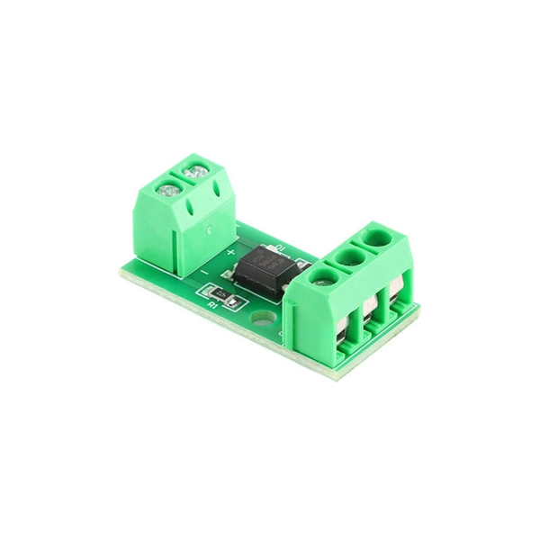
One approach to test the total protection system is to use primary injection techniques (see appendix H) that trigger protective relays and lockout relay, trip circuit breakers, and initiate annunciations and indications. If applicable, documentation is required detailing how verified protection segments overlap to ensure there is not a gap. The purpose of this Standard Work Practice (SWP) is to standardise and describe the method for testing of Ergon Energy protection relays for commissioning purposes. This SWP should be interpreted in conjunction with Standard for Substation Protection (V1. From a technician's perspective, master the unique skill of testing protection. When the transformer wiring type is Y/Y (Y0), the test wiring is very simple: when testing phase A, the tester IA is connected to the phase A of the high voltage side, and the tester IB is connected to the phase a of the low voltage side. After the neutral line of the high and low voltage sides is. Function: Use electronic components like transistors to perform switching. Applications: Frequency, undervoltage, and overcurrent protection.
[PDF Version]
-
Steps for Short Circuit Calculation in Relay Protection
Voltage levels, transformer ratings and impedances, line lengths and impedances, generator/motor data. Select fault location Choose busbars or nodes where faults will be studied. Apply IEC. A short circuit occurs when an unintended low-impedance path forms between: Physical Causes: Critical Applications: ⚠️ Safety Critical: Incorrect fault current calculations can result in explosive equipment failures, arc flash incidents causing severe burns, and system-wide cascading failures. The principle is to grade the operating times of the relays in such a way that. The scope of study involves calculating the settings for protective relays to achieve selectivity during faults ocurring in the electrical network for the 13. In OC relays the coordination is based on the relay time-current characteristics of instantaneous and/or time delay units. Instantaneous units should be set so they. As of this update, Service Disconnect Switches, Surge Protective Devices, Switchboards, Switchgear, and Panelboards, Industrial Control Panels, Motor Controllers, Elevators, Industrial Machinery, and Transfer Equipment are all required to have short-circuit current ratings.
[PDF Version]
-
Relay Protection Circuit Diagram Numbering Rules
This handbook covers the code of practice in protection circuitry including standard lead and device numbers, mode of connections at terminal strips, colour codes in multicore cables, dos and donts in execution. Also principles of various protective relays and schemes including special protection. For power grid systems, ANSI and IEEE functional number codes dictate the use and restrictions of both the devices themselves, as well as the functions of those devices within the scope of a circuit. These devices include switches, disconnects, circuit breakers, generators, and motors. One is given in ANSI Standard and uses a numbering system for various functions. The functions are supplemented by letters where amplification of the function is required.
-

Circuit Breaker Relay Protection Equipment Model
Microprocessor-based solid-state digital protection relays now emulate the original devices, as well as providing types of protection and supervision impractical with electromechanical relays.OverviewIn, a protective relay is a device designed to trip a when a is detected. The first protective relays were electromagnetic devices, relying on coils operating on moving par. Electromechanical protective relays operate by either, or. Unlike switching type electromechanical with fixed and usually ill-defined operating voltage thresholds. Electromechanical relays can be classified into several different types as follows: "Armature"-type relays have a pivoted lever supported on a hinge or knife-edge pivot, which carries a moving contact. These relays may.