-
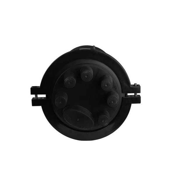
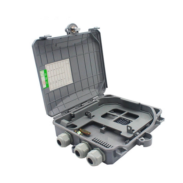
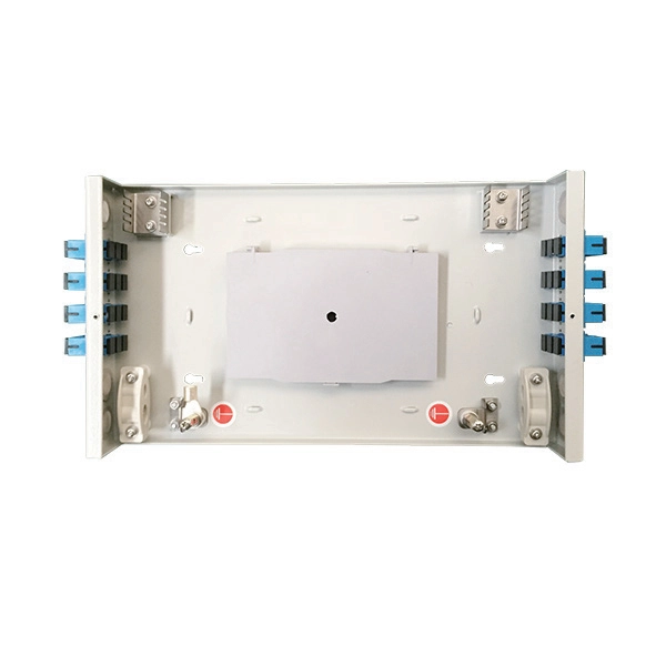
Fiber Optic Terminal Box Serial Connection Method
In network cabling, outdoor connections generally use fiber optic cables. When these optical fibers are installed or laid out, a Fiber Termination Box, or FTB, is used to distribute and protect the optical fiber link.
-
Grounding method for motor distribution box
The most common method of providing for grounding in NEMA motors is a ground lug under one of the conduit box mounting bolts. This is standard in CORRO-DUTY® motors. Each DISTRIBUTION BOX and controller must be grounded. 26 mm 2 (10 AWG) ground wire must be used, and in all other markets a 6 mm 2 must be used. Grounding of the units: Attach a ground wire from one of. Grounding is a mechanism to protect distribution equipment and people under normal operating conditions, abnormal operational (overcurrent and overvoltage) responses, and hazardous conditions such as shocks. Next, we describe directional elements suitable to provide ground fault protection in solidly- and low-impedance grounded distribution systems. The specific neutral grounding method chosen by the utility can have significant impacts on reliability of service, safety, protection coordination, power.
[PDF Version]
-
Indoor 4-core optical fiber cable pigtail splicing method
Splice pigtails onto existing fiber cables with a fusion splicer — the most time-efficient field termination method, with no polishing consumables or cure time. Field-terminating connectors is a meticulous, high-pressure process where even a tiny mistake can force you to cut the fiber and start all over again. The most efficient way to terminate a. Executive Summary: A fiber optic pigtail is one of the most commonly specified yet least understood components in structured cabling. It is typically used in cabling work area subsystems. When Do You Need to Splice Fiber Optic Cables? Fiber optic cable splicing.
-
Calculation method for beam splitter
A beam splitter divides incident light into reflected and transmitted beams at a specified R/T ratio. For a lossless beam splitter, R + T = 1. One of the biggest challenges for modeling such a system is that multiple ray paths cannot be simultaneously traced in Sequential Mode. Thus, multiple configurations are needed to trace rays along both the transmitted and. Three techniques to model diffractive beam splitters – two in Sequential and one in Non-Sequential modes: 2. Method A: Diffraction Grating surface and multi-configuration 2. Development steps Inserting general parameters for simulation (wavelength, aperture,. Field 1 evolves as E1 ! T E3 + RE4, where T; R are the transmission and re ection coe cients for the beam splitter. The transformation matrix is then given by. Separate (focused) beams or light points are of interest for a wide range of applications, whether for manufacturing processes, for special fiber coupling, for face recognition systems or light marker generation.
[PDF Version]
-
Installation method of cable tray in distribution box
Spring knot is used to connect cable tray or trunking to channel. Approved and correct fittings are used. Installed containments are free of damages. Whether you're building a commercial setup or upgrading an industrial plant, proper cable tray installation ensures neat wiring, safe access, and easy maintenance. But before you lay the first tray or clamp down a single cable, you need a solid plan. This guide breaks down the process step by step. This guide covers the critical steps, from selecting the right electrical cable tray and performing accurate cable fill. maintain spacing or to keep cables in place when the tray is ect the minimum bend ra-dius for cables as they exit the bottom of the cable tray. A rung spacing of 6 to 9 inches (150 to 230 mm) is preferable when the cable tray cont d for instrumentation and control applications that require. Below is the detailed cable tray installation method statement not only for cable tray but also applicable for GI ladder and trunking for indoor and outdoor applications and in service rooms like pump rooms, electrical rooms and plant rooms etc.
[PDF Version]