-
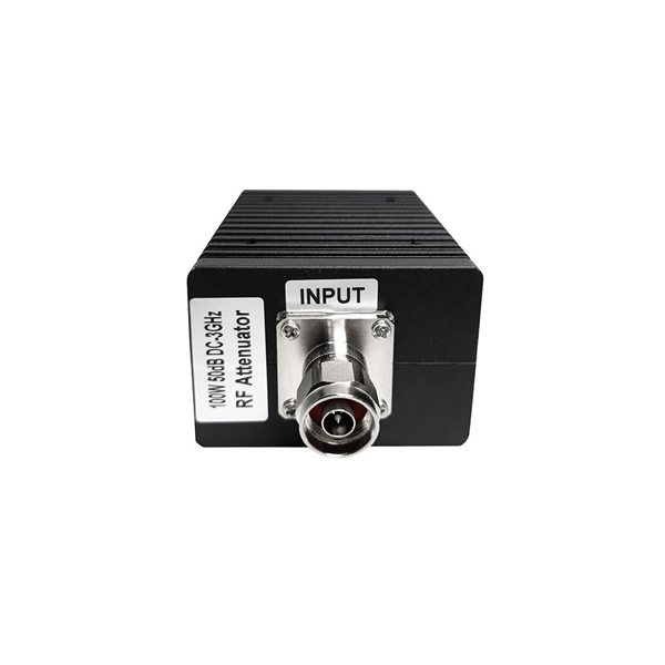
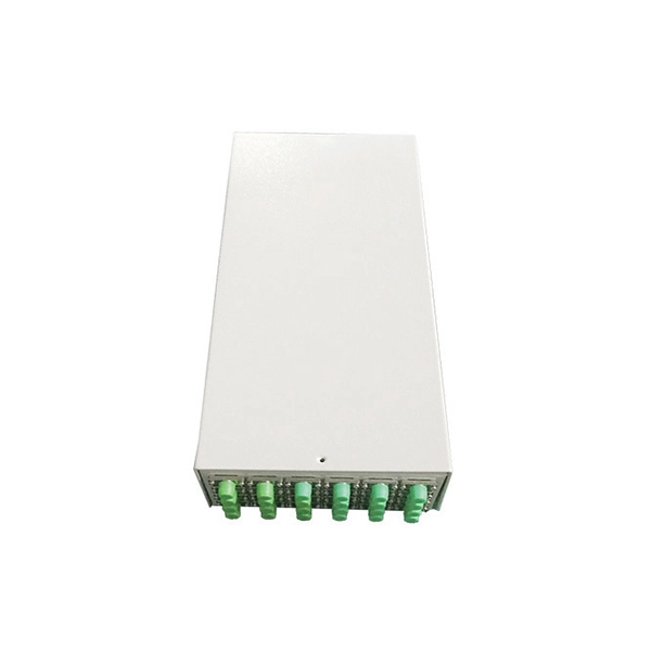
Steps for troubleshooting optical modules
Ensure module is fully seated, check optical power levels (Tx & Rx), replace suspect patch cord. Vendor incompatibility, outdated device firmware, incorrect module type for slot. Consult vendor compatibility list, upgrade device firmware, confirm module form-factor (SFP . Customers in the use of optical modules will more or less encounter a variety of failure problems, such as optical module model selection is correct, the use of jumper is correct and some common problems, customers have the ability to judge and have a clear solution, but for some of the use of. Based on typical issues encountered with optical modules in daily switch applications, this document summarizes basic troubleshooting steps for resolving common faults: 1. However, during installation and daily operation, various issues may arise. Therefore, understanding common optical module. The Ultimate Guide to Principles, Types, and Troubleshooting Optical Modules (also known as Optical Transceivers) are critical components in fiber optic communication systems. It is important to understand how to.
[PDF Version]
-
Troubleshooting optical fiber cables
Successful fiber optic troubleshooting relies heavily on having the right diagnostic tools. These specialized instruments allow technicians to “see” the light signal, measure its strength, and locate faults within the fiber. These high-speed, high-capacity communication networks are increasingly replacing copper cables, offering superior performance and. Fiber optic troubleshooting is the systematic process of identifying, diagnosing, and resolving problems within fiber optic communication networks. These networks are the backbone of modern data transmission, offering incredible speeds and bandwidth. However, even the most robust systems can. Problems within a fiber link can occur due to a wide variety of reasons.
-
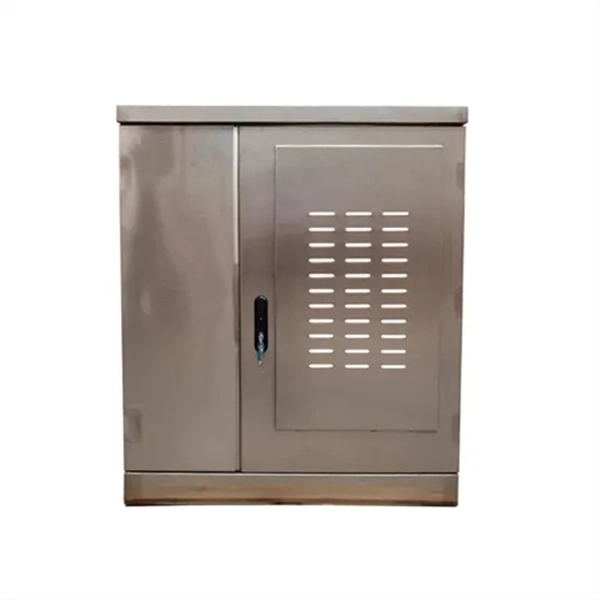
What are the basic dimensions of the outdoor server rack
The three primary dimensions to consider are rack height (measured in rack units or U), rack width (most commonly the industry-standard 19-inch format), and rack depth (typically ranging from 24 inches to 48 inches). Choose size based on equipment type, cooling, space, and future growth. Most IT environments default to 42U, 19-inch width, and 1000–1200 mm depth unless space constraints or special equipment dictate. Rack height is measured in rack units (U) — 1U = 1. Standard width is 19 inches (EIA-310 compliant), while outer widths vary (e. 5″) to allow space for cable management and airflow. Rack depth matters for. AZE's 24U IP65 Outdoor Server Enclosures are designed to protect your sensitive network equipment from harsh environments,with waterproof and dustproof features to safeguard it from the elements, while still keeping the equipment secure outside. Includes: locking door with gaskets and. Below is a comprehensive, fully detailed guide covering all standard server rack sizes, form factors, height considerations, depth classifications, and best-practice configuration approaches for professional environments.
[PDF Version]
-
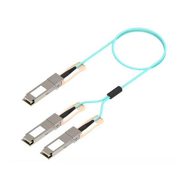
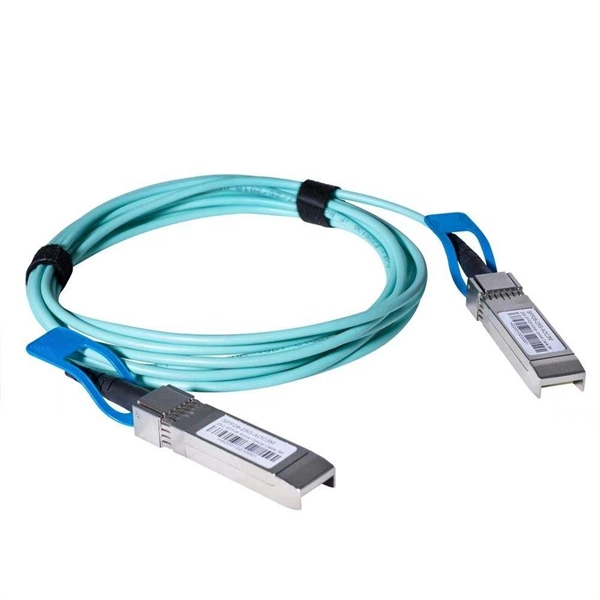
Selection Guide for QSFP Active Optical Modules for Cloud Computing
This QSFP module guide delivers a technical deep dive into the most prevalent QSFP transceivers, their specs, real-world deployments, and practical buying advice. Whether you're upgrading to 100G or optimizing your 40G links, this article is tailored for network architects, engineers, and system. The Ultimate Guide to QSFP Optical Modules: 40G to 800G Interconnect Evolution In today's digital era sweeping across the globe, data centers—the core hubs of information processing—have an insatiable demand for high-speed, high-density data transmission solutions. By increasing channel density, it enables higher port utilization and seamless upgrades on existing infrastructure. As a core component of high-speed networks, QSFP-DD. As high-speed networks continue to evolve, optical transceivers like QSFP-DD, QSFP28, QSFP56, SFP56, and SFP28 have become the core components enabling scalable and efficient connectivity across data centers and telecom environments. Below is a detailed breakdown of each module series.
[PDF Version]
-
Should the cable management rack be installed in the front or the back
Leave space for cable management —especially in the back. Ensure front-to-back airflow by leaving gaps or using filler panels. This method helps maintain neatness and accessibility within the rack while ensuring efficient airflow and ease of maintenance. Both overhead and under floor pathways should be designed to support the weight of cables in the initial installation and it should also facilitate the addition of future cables. With proper design and structured tools, it helps organize cables, ensure stable signal transmission, simplify maintenance, and improve overall system. Here are some best practices for rack placement: Implementing hot and cold aisle containment is a fundamental strategy for improving airflow and cooling efficiency. The racks should be positioned in a way that optimizes.
-
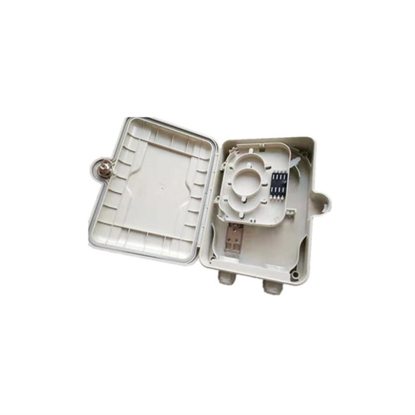
The power cable enters from the bottom of the distribution box
Cables can enter the structure from the floor (bottom entry) or from above (top entry. ) Distribution structures divide and send power to branch circuit protection devices and then to branch circuits to power downstream loads. Power. When installing a new overhead combination service for a residential service replacement we were told by the EI that we could not install our romex cables coming from under the house in a single 2" pipe approx. The scope of the article includes electrical requirements related to: Below is a complete overview. Once the box is securely in place, it's time to bring in the cables that will carry current from the main panel. Escape will cancel and close the window. Power from the utility company is typically delivered through three large conductors, which may enter the house overhead or underground. Overhead service. Fixed to a wall—This is a common approach for small electrical distribution boards. For bottom entry, the floor can incorporate a trench or false floor, which is often simpler since it provides.
[PDF Version]
-
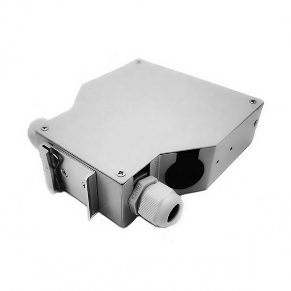
Spacing of the side of the distribution box
Side clearance: There should be a minimum of 30 inches of clearance from the sides of all electrical equipment, but in no case less than the width of the equipment itself. This is referred to as the side-to-side working space. In industrial power distribution systems, cable distribution boxes (also known as power distributor boxes, distribution electrical boxes, or electrical power distribution boxes) are the core hub of power transmission, branching, and protection. Its layout directly affects the efficiency of the. NEC Article 314 establishes requirements for the installation and use of electrical boxes, conduit bodies, fittings, and handhole enclosures. NEC Article 408. Boxes distribute low currents in an area equipped with 1 to 12 RJ 45 sockets. They centralise connections to ensure flexibility and that the installation is up to date.
[PDF Version]
-
Selection Guide for OSFP and QSFP Optical Modules Used in Supercomputing Centers
This article compares OSFP and QSFP-DD in terms of physical dimensions, power and thermal characteristics, and compatibility, providing practical guidance for data center and network infrastructure planning. In the rapidly evolving landscape of high-performance computing and AI infrastructure, NVIDIA optical transceivers have emerged as critical components for enabling next-generation 800G network deployments. This guide gives you the complete picture. Our study of OSFP transceiver technology will begin with basic concepts and continue until we reach advanced technical. Today's mainstream 400G optical modules use three primary form factors: QSFP-DD, OSFP, and QSFP112. This article provides a comprehensive comparison of the three. In 2025, the optical transceiver market has shifted decisively. On the path to the 400G era, different form factors act as distinct engines, delivering.
[PDF Version]