-
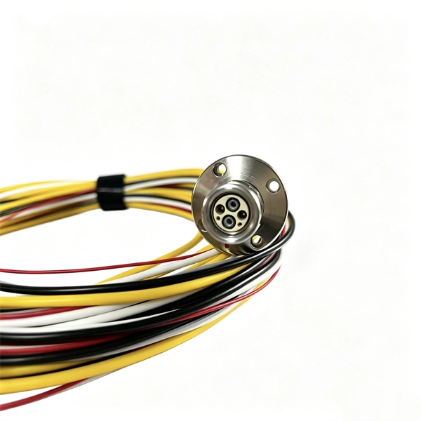
Connect the copper busbar in the computer room to the ground wire of the distribution box
Grounding electrode conductor (GEC) – wire connecting the panel to the ground rod. Drive a ground rod into the earth near the panel. This position is the connection point of the grounding wire in the. The Mesh-BN is the backbone of the bonding system, designed to ensure a uniform electrical potential across the entire data center. Now, let's. An electrical ground bus bar is a conductive bar made from materials like copper or aluminum, and it serves as the central point for connecting multiple grounding conductors in an electrical system. Grounding is one of the most crucial safety measures in electrical installations, and the bus bar. AI workloads, GPU clusters, and high-performance computing are pushing server rack power density to new extremes — from the historical 5-7 kW per rack to 20-40 kW or more. Our kits are available as one kit per rack to allow for ease of stocking and reordering.
[PDF Version]
-
What type of copper is used in network patch panels
Twisted-pair copper patch panels are built to a certain Ethernet specification, such as Cat 5e, Cat 6, or Cat 6a, and though they are backwards compatible, use different gauges of copper wiring to facilitate the greater bandwidth and shielding of the higher categories. In each case, the patch panel. Today, various styles of copper patch panels can be found in the market, such as shielded or unshielded patch panel, flat or angled patch panel, etc. Their design, material, and compliance directly affect signal integrity, insertion loss, crosstalk, manageability, and fire safety.
-
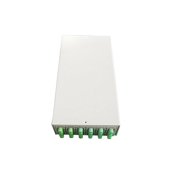
Fiber optic panel IP67 vs copper cable
Fiber optic cables are much thinner and lighter than copper cables. They are also more flexible and take up less space, making them easier to install and manage. Fiber optic tends to be the more premium solution, while copper wiring is far more common, but why is that? What are the differences between these two cable types, and why might you want to pick one over the other? Here's everything you need to know about fiber vs. copper cables, to help you pick. This guide compares copper vs fiber, highlighting their strengths and limitations across transmission distance, power delivery, device density, and practical deployment scenarios. Understanding these factors can help make informed decisions, ensuring efficient and reliable network infrastructures. Networking cables are the foundation of modern communication systems, connecting devices across offices, homes, and data.
[PDF Version]
-
What type of copper is used for the small busbar in a high-voltage switchgear
ETP copper, known as C11000, is widely used for busbars due to its high conductivity and affordability. Although cost-effective, ETP copper is prone. Copper busbars are essential components in electrical power distribution systems, widely used in switchgear, substations, panel boards, and industrial electrical installations. They are easy to install and offer a high surface area, which is great for heat dissipation. Their design allows for simple connections and can be easily. The most common type of copper used. With a minimum copper content of 99. aluminum's 61%) but aluminum providing significant weight reduction (66% lighter) and cost savings (30-50% cheaper).
-
Should the cable management rack be installed in the front or the back
Leave space for cable management —especially in the back. Ensure front-to-back airflow by leaving gaps or using filler panels. This method helps maintain neatness and accessibility within the rack while ensuring efficient airflow and ease of maintenance. Both overhead and under floor pathways should be designed to support the weight of cables in the initial installation and it should also facilitate the addition of future cables. With proper design and structured tools, it helps organize cables, ensure stable signal transmission, simplify maintenance, and improve overall system. Here are some best practices for rack placement: Implementing hot and cold aisle containment is a fundamental strategy for improving airflow and cooling efficiency. The racks should be positioned in a way that optimizes.
-
Fixing bracket on the back of the distribution box
How to install the mounting bracket? Many engineers don't know how to install this accessory. With the latest design, it can be confusing. Mounting bracket is a flexible structure, which makes it easy to adjust or replace the electrical components. All the components, wires and connections are under the protective cover due to the same height. The BBT-HF telescoping bracket, used with the BBA and BBA-4 box mounting brackets, provides an extremely flexible, fast rough-in solution. more Charlie DIYte (CharlieDIYte) tagged products below. Make sure the walls are strong enough to bear the weight of the box and electrical equipment. Ground. Electrical box screw mounts broke, can it be fixed without tearing up wall? I was unplugging an appliance in the kitchen when the whole outlet pulled out of the wall. Second photo shows my temp.
-
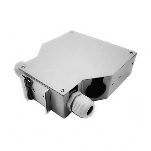
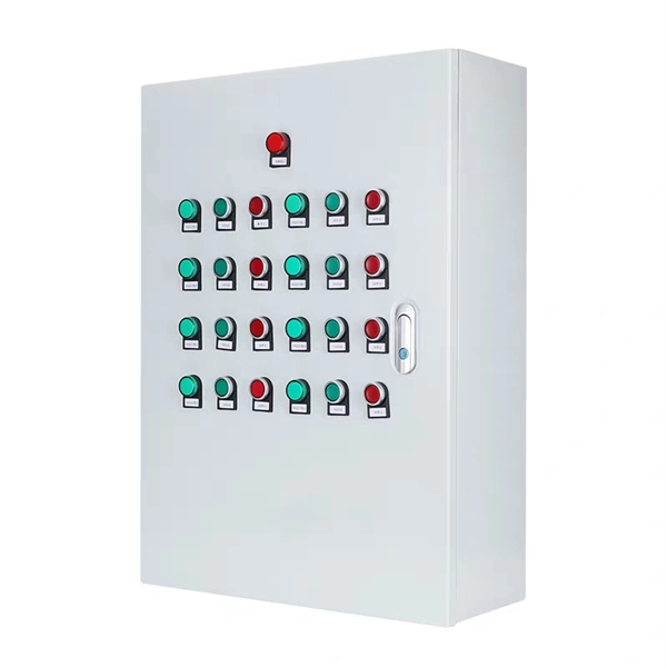
Spacing of the side of the distribution box
Side clearance: There should be a minimum of 30 inches of clearance from the sides of all electrical equipment, but in no case less than the width of the equipment itself. This is referred to as the side-to-side working space. In industrial power distribution systems, cable distribution boxes (also known as power distributor boxes, distribution electrical boxes, or electrical power distribution boxes) are the core hub of power transmission, branching, and protection. Its layout directly affects the efficiency of the. NEC Article 314 establishes requirements for the installation and use of electrical boxes, conduit bodies, fittings, and handhole enclosures. NEC Article 408. Boxes distribute low currents in an area equipped with 1 to 12 RJ 45 sockets. They centralise connections to ensure flexibility and that the installation is up to date.
[PDF Version]