-
How to distribute current in the distribution box circuit
Busbars are metal strips or bars that distribute electrical power throughout the distribution box. They carry current from the main switch to individual circuit breakers, providing a reliable connection point for all circuits. Current distribution refers to how this electrical charge flow is divided and allocated among the various components and pathways in a system. Understanding this process is foundational to. A multiwire branch circuit has two or more ungrounded conductors that have a voltage between them, and a neutral conductor that has equal voltage between it and each ungrounded conductor of the circuit. These include requirements for conductor sizing, overcurrent protection, identification, GFCI and AFCI protection, receptacle outlets, and lighting outlets. A “branch circuit” consists of the conductors. Hey, in this article we are going to see the Single Phase Distribution Box Wiring Diagram and Connection Procedure.
[PDF Version]
-
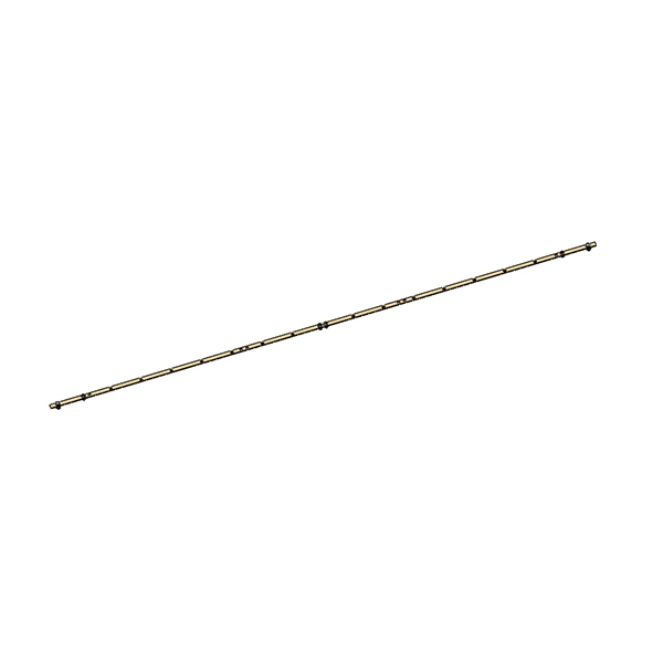
Tube-type busbars and current carrying capacity
The current-carrying capacity of a busbar depends on its cross-sectional area, the ambient temperature, and how it's installed. For example, a 50 mm x 10 mm copper busbar in open air can typically carry about 1000 A, assuming an ambient temperature of 35°C and a temperature rise. Busbar sizing by current and temperature rise is therefore not a formality — it is a safety-critical engineering process governed by IEC 61439-1 and equivalent national standards. This guide walks through every step, from material selection and conductor dimensioning to ampacity tables, derating. This guide explains the busbar size chart, current ratings, materials, and how to choose the right busbar for electrical applications. Supports rectangular and round shapes. The electrical power system consists of many incoming & outgoing feeder connections, for which busbars are necessary.
[PDF Version]
-
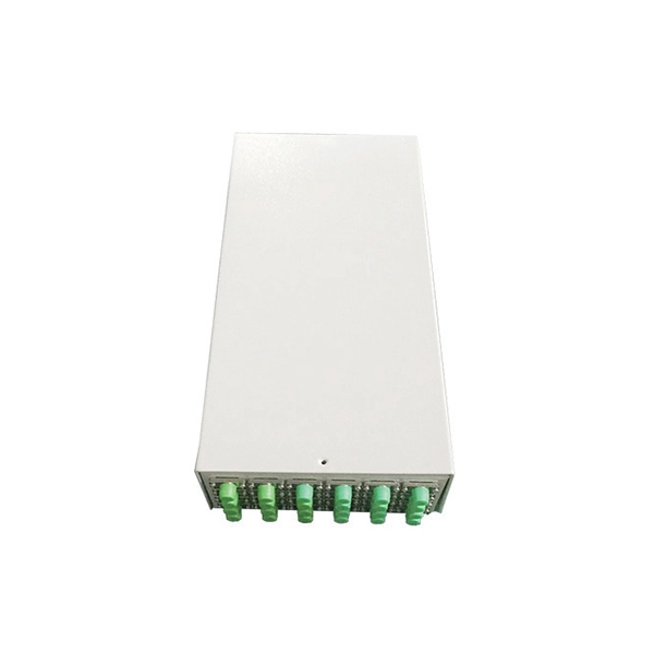
Wiring of residual current circuit breaker in distribution box socket
In this video, I'll show you the complete wiring diagram of a home distribution board (DB). You'll learn how to connect the main circuit breaker (MCB), residual current device (RCD), and individual circuit breakers for lighting, sockets, and appliances. This guide provides a detailed, professional procedure for installing a Residual Current Circuit Breaker (RCCB)—a device essential for protecting people from the severe danger of electric shock. #dbbox #distribution #home #house. A distribution board or distribution box is where the main power supply is distributed to multiple loads. You will learn to build a safe, efficient, and professional electrical system today.
-
How much current does the distribution box carry
Electric power distribution is the final stage in the. Electricity is carried from the to individual consumers. Distribution connect to the transmission system and lower the transmission voltage to medium voltage ranging between 2 and 33 kV with the use of. Primary distribution lines carry this medium voltage power to located.
-
High Current Relay Protection Tester
The CMC 356 is the universal six-phase testing solution for all generations and types of protection relays, where highest versatility, amplitude and power are required.
-

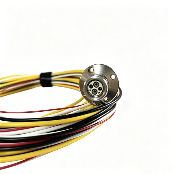
Relay protection voltage and current signals
A protection relay is a crucial component of electrical systems that safeguard infrastructure, employees, and equipment from electric problems and malfunctions. It. Reference Design to Measure AC Voltage and Current in Protection Relay With Delta-Sigma Chip Diagnostics (Rev. A) This high-accuracy analog front-end (AFE) reference design measures analog input performance and includes chip diagnostics to help identify power system failures using AC voltage and. The rectangular devices are test connection blocks, used for testing and isolation of instrument transformer circuits. In electrical engineering, a protective relay is a relay device designed to trip a circuit breaker when a fault is detected. ABB Type SAB Current Transformer CT's transform line current down to a signal level that is acceptable to the relay.
-

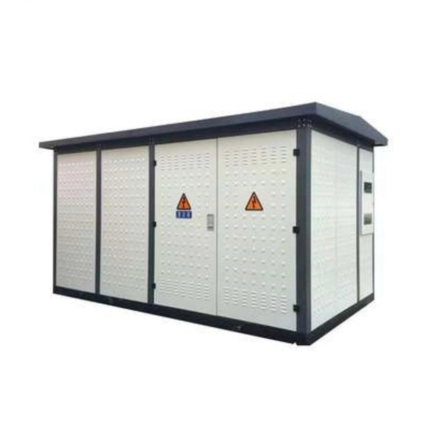
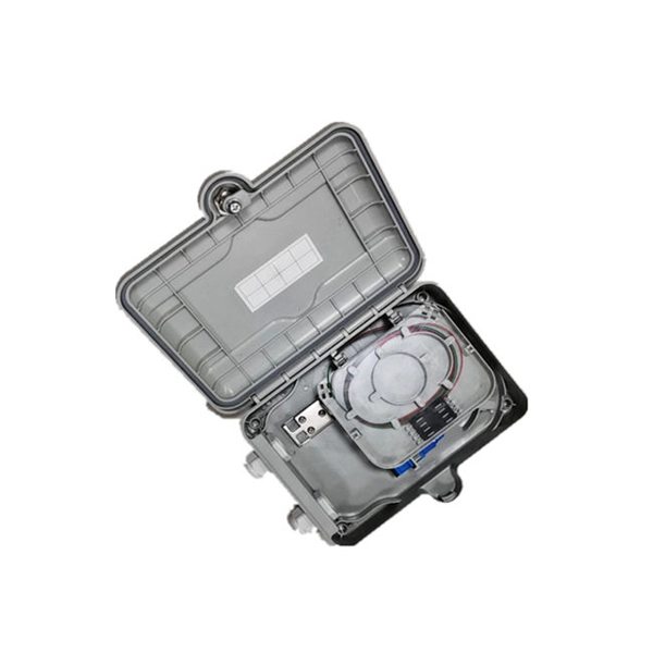
The power cable enters from the bottom of the distribution box
Cables can enter the structure from the floor (bottom entry) or from above (top entry. ) Distribution structures divide and send power to branch circuit protection devices and then to branch circuits to power downstream loads. Power. When installing a new overhead combination service for a residential service replacement we were told by the EI that we could not install our romex cables coming from under the house in a single 2" pipe approx. The scope of the article includes electrical requirements related to: Below is a complete overview. Once the box is securely in place, it's time to bring in the cables that will carry current from the main panel. Escape will cancel and close the window. Power from the utility company is typically delivered through three large conductors, which may enter the house overhead or underground. Overhead service. Fixed to a wall—This is a common approach for small electrical distribution boards. For bottom entry, the floor can incorporate a trench or false floor, which is often simpler since it provides.
[PDF Version]
-
Fixing bracket on the back of the distribution box
How to install the mounting bracket? Many engineers don't know how to install this accessory. With the latest design, it can be confusing. Mounting bracket is a flexible structure, which makes it easy to adjust or replace the electrical components. All the components, wires and connections are under the protective cover due to the same height. The BBT-HF telescoping bracket, used with the BBA and BBA-4 box mounting brackets, provides an extremely flexible, fast rough-in solution. more Charlie DIYte (CharlieDIYte) tagged products below. Make sure the walls are strong enough to bear the weight of the box and electrical equipment. Ground. Electrical box screw mounts broke, can it be fixed without tearing up wall? I was unplugging an appliance in the kitchen when the whole outlet pulled out of the wall. Second photo shows my temp.
-
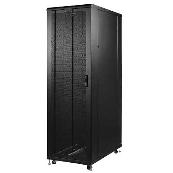
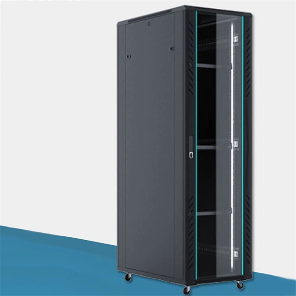
Should the cable management rack be installed in the front or the back
Leave space for cable management —especially in the back. Ensure front-to-back airflow by leaving gaps or using filler panels. This method helps maintain neatness and accessibility within the rack while ensuring efficient airflow and ease of maintenance. Both overhead and under floor pathways should be designed to support the weight of cables in the initial installation and it should also facilitate the addition of future cables. With proper design and structured tools, it helps organize cables, ensure stable signal transmission, simplify maintenance, and improve overall system. Here are some best practices for rack placement: Implementing hot and cold aisle containment is a fundamental strategy for improving airflow and cooling efficiency. The racks should be positioned in a way that optimizes.
-
Low-voltage busbar current carrying capacity standard
For busbar sizing, the primary references are IEC 61439 (for low-voltage switchgear and controlgear assemblies) and IEC 60287 (for current-carrying capacity of cables). IEC 61439 is a standard developed by the International Electrotechnical Commission (IEC) that covers design verification for low-voltage electrical products and assemblies. Special service conditions, for example in ships and in rail vehicles provided that the other relevant specific requirements are complied with. Current load capacity is the maximum value of the current flowing through the conductor in an unlimited period of time in certain conditions – it will.
-
Working principle of thermal current relay protection device
The thermal relay working principle is that whenever a bimetallic strip in the thermal relay is heated up through a heating coil then it bends & makes normally open (NO) contacts. This article discusses an overview of a thermal relay – working with applications. What is a Thermal Relay? Thermal relay. A thermal relay is an essential component in electrical engineering, designed to protect electric motors and other electrical devices from overloads that might cause damage due to excessive current flow. Tips on connecting and competent configuration are given.