-
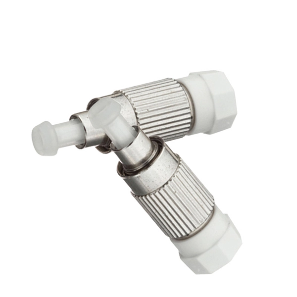
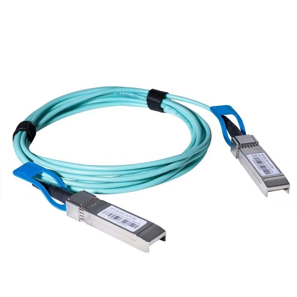
Working principle of 10 Gigabit fiber optic patch cord
The functioning of a fiber optic patch cord relies on its construction. It consists of a core with a high refractive index, enveloped by a coating featuring a lower refractive index. This assembly is fortified using aramid yarns and encased within a protective jacket. These cables, also known as fiber optic patch cables or jumpers, are designed to transmit information as pulses of light, offering unparalleled speed, bandwidth, and immunity to electromagnetic interference compared to traditional copper cables. As network demands continue to explode, selecting the. Key factors to consider in the design of 10 Gigabit Ethernet networks are: The network topology, including operating distances, splice losses and numbers of connectors (i. Fiber optic patch cables are found almost everywhere; cable television networks (CATV), data centers, computer networks, and telephone networks.
[PDF Version]
-

Switches are all 10 Gigabit optical
To implement different 10GbE physical layer standards, many interfaces consist of a standard socket into which different physical (PHY) layer modules may be plugged. PHY modules are not specified in an official standards body but by (MSAs) that can be negotiated more quickly. Relevant MSAs for 10GbE include (and related X2 and XPAK), and. When choosing a PHY.
-
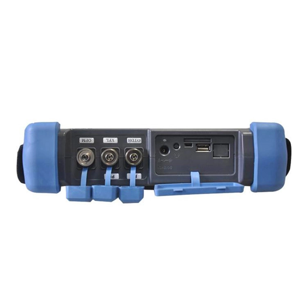
How to connect the 10 Gigabit Ethernet cable to the fiber-to-electrical port module
A special 10G Copper RJ-45 Transceiver (10G-SFP-T) is required to connect the SFP+ port to RJ45. It allows connecting a server/storage side Cat6/7 cable to an SFP+ port transceiver. An SFP module (or optical transceiver) converts electrical signals from network devices (switches, routers) into optical signals for fiber transmission and vice versa. 1G/10G SFP+: Standard for Gigabit and 10 Gigabit Ethernet. These transceiver modules are hot-swappable input/output (I/O) devices that plug into 100BASE, 1000BASE and 10GBASE ports (for SFP+), which connect the module port with the fiber-optic or copper network. 4ft (30m) * using Cat6a/Cat7 or above cable for 10G connection in various applications. In this video, we'll guide you through building a high-speed 10G LAN by connecting two fiber switches. Finally, check the transmit (TX) and receive (RX) paths to ensure that signals are aligned.
[PDF Version]
-
Near the fireproof bridge in Ukraine
On 12 August, the bridge was the target of a missile attack. The bridge was fully reopened on 14 October. Another explosion occurred on 3 June 2025 near the support pillars, but by evening traffic returned to normal. Ukraine claimed responsibility for all three explosions.OverviewThe Crimean Bridge, also called Kerch Strait Bridge or Kerch Bridge, is a pair of parallel bridges, one for a four-lane road and one for a double-track railway, spanning the between the had been considered since the early 20th century. During World War II the German built a over the strait. Finis. After the annexation, Russian officials looked at various options for connecting Crimea to the Russian mainland, including a tunnel, but eventually settled on a bridge. The bridge spans the between the.
-
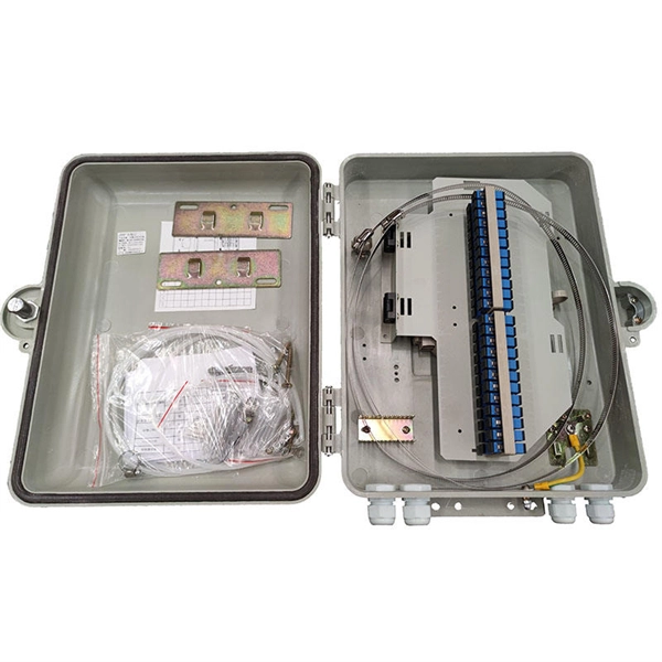
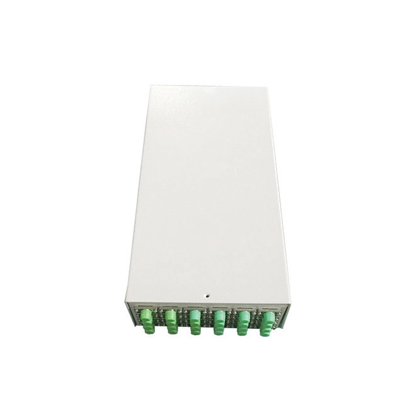
Spacing of the side of the distribution box
Side clearance: There should be a minimum of 30 inches of clearance from the sides of all electrical equipment, but in no case less than the width of the equipment itself. This is referred to as the side-to-side working space. In industrial power distribution systems, cable distribution boxes (also known as power distributor boxes, distribution electrical boxes, or electrical power distribution boxes) are the core hub of power transmission, branching, and protection. Its layout directly affects the efficiency of the. NEC Article 314 establishes requirements for the installation and use of electrical boxes, conduit bodies, fittings, and handhole enclosures. NEC Article 408. Boxes distribute low currents in an area equipped with 1 to 12 RJ 45 sockets. They centralise connections to ensure flexibility and that the installation is up to date.
[PDF Version]
-
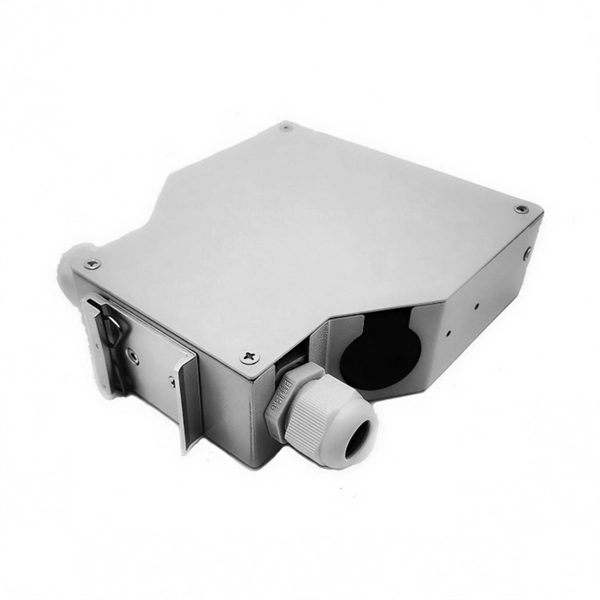
The power cable enters from the bottom of the distribution box
Cables can enter the structure from the floor (bottom entry) or from above (top entry. ) Distribution structures divide and send power to branch circuit protection devices and then to branch circuits to power downstream loads. Power. When installing a new overhead combination service for a residential service replacement we were told by the EI that we could not install our romex cables coming from under the house in a single 2" pipe approx. The scope of the article includes electrical requirements related to: Below is a complete overview. Once the box is securely in place, it's time to bring in the cables that will carry current from the main panel. Escape will cancel and close the window. Power from the utility company is typically delivered through three large conductors, which may enter the house overhead or underground. Overhead service. Fixed to a wall—This is a common approach for small electrical distribution boards. For bottom entry, the floor can incorporate a trench or false floor, which is often simpler since it provides.
[PDF Version]
-
Should the cable management rack be installed in the front or the back
Leave space for cable management —especially in the back. Ensure front-to-back airflow by leaving gaps or using filler panels. This method helps maintain neatness and accessibility within the rack while ensuring efficient airflow and ease of maintenance. Both overhead and under floor pathways should be designed to support the weight of cables in the initial installation and it should also facilitate the addition of future cables. With proper design and structured tools, it helps organize cables, ensure stable signal transmission, simplify maintenance, and improve overall system. Here are some best practices for rack placement: Implementing hot and cold aisle containment is a fundamental strategy for improving airflow and cooling efficiency. The racks should be positioned in a way that optimizes.