-
Relay Protection Test Wiring Method
One approach to test the total protection system is to use primary injection techniques (see appendix H) that trigger protective relays and lockout relay, trip circuit breakers, and initiate annunciations and indications. If applicable, documentation is required detailing how verified protection segments overlap to ensure there is not a gap. The purpose of this Standard Work Practice (SWP) is to standardise and describe the method for testing of Ergon Energy protection relays for commissioning purposes. This SWP should be interpreted in conjunction with Standard for Substation Protection (V1. From a technician's perspective, master the unique skill of testing protection. When the transformer wiring type is Y/Y (Y0), the test wiring is very simple: when testing phase A, the tester IA is connected to the phase A of the high voltage side, and the tester IB is connected to the phase a of the low voltage side. After the neutral line of the high and low voltage sides is. Function: Use electronic components like transistors to perform switching. Applications: Frequency, undervoltage, and overcurrent protection.
[PDF Version]
-
How to test the continuity of pigtail fiber
A visual fault locator (VFL) makes use of a visible spectrum laser light to test the continuity of the fiber and detect fault conditions. There are two reasons we may want to test bare fiber, by that we mean fiber that has not been terminated in connectors but is simply plain optical fiber, The first one is to ensure the fiber or cable being manufactured meets its specifications, as is done by every manufacturer. Fiber optic. The Optical Time Domain Reflectometer (OTDR) will be used to test splice loss and to conduct span analysis. An Optical Power Meter and Laser Light Source will be used to measure power loss on each completed ring or distribution span to verify continuity between fibers (no fibers incorrectly spliced. A visual check is often the first step when diagnosing a defective fiber pigtail. Continuity testing verifies that the fiber is intact and that light can pass through from one end to the other without any blockages. This comprehensive guide will equip you with the knowledge and skills to accurately assess the integrity of a pigtail, helping you identify issues.
[PDF Version]
-
Fiber Optic Cable Tension Load Test Standard
This Applications Engineering Note (AEN 135) explains and recommends standard measurement methods for characterizing optical fiber system performance. FOA procedures, such as OFSTP-7 (single-mode) and OFSTP-14 (multimode), align with TIA and IEC standards. They describe how to set a '0 dB' reference, control mode power distribution, and use proper wavelengths. These procedures ensure you get consistent, repeatable results that meet international. d suppliers of electrical construction services. We're here to support your fiber network needs.
-
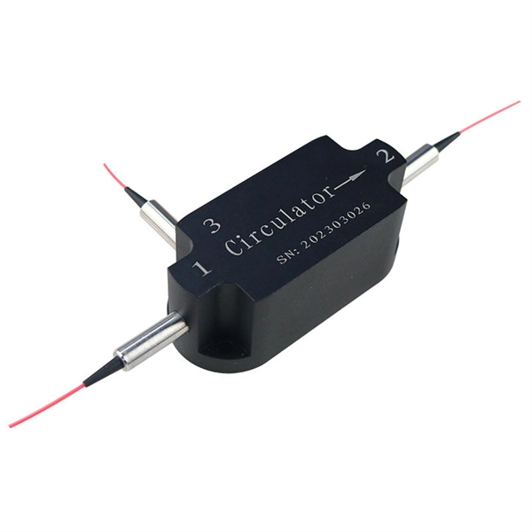
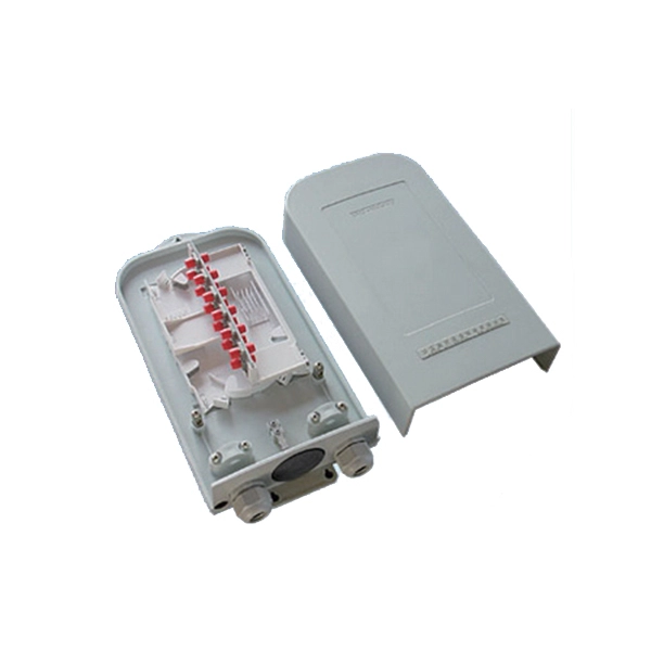
How to test a 1 2 beam splitter
To accurately measure optical splitter loss, utilize optical test equipment like power meters and spectral analyzers. Here's how: Measure the optical power at both the input and output ports of the splitter. What are Optical Splitters? The fiber optic splitter is a device used in fiber optic networks to divide a single optical signal into multiple signals. A beam splitter or beamsplitter is an optical device that splits a beam of light into a transmitted and a reflected beam. In its. This article explains how to create a beam splitter cube in Sequential Mode. Note that jT j2 is the transmitted intensity. I have been looking and either I can't find what I am looking for, or I just get. Page 5 Outline of Product Manual Outline of Product Manual The entire documentation of the hydraulic stone and concrete splitter includes: Product Manual – Information Manual (IM) – for the operator of the device – Operating Manual (OM) – for the operator and –. Table of Contents (IM) Table of.
[PDF Version]
-
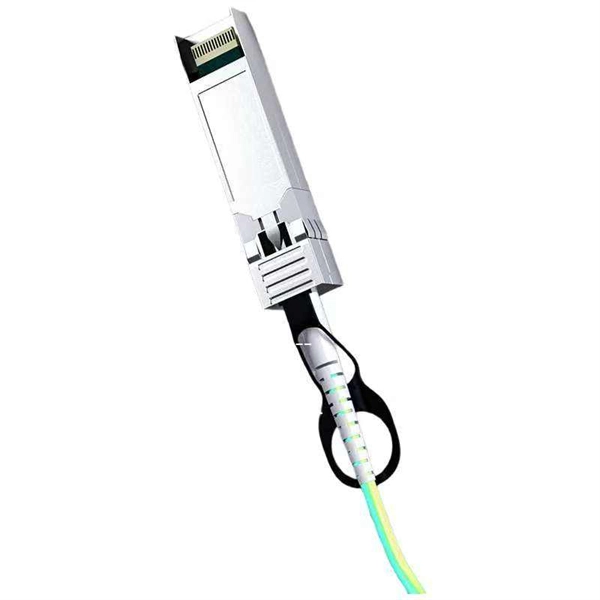
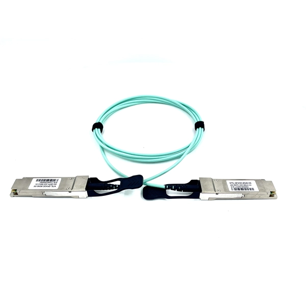
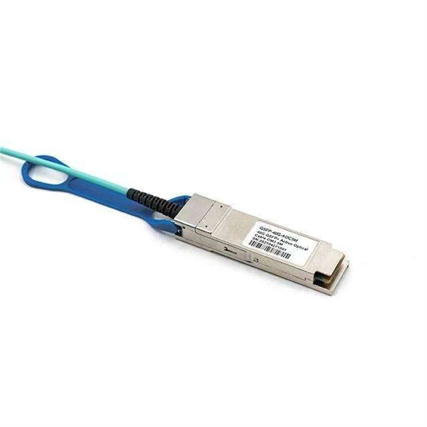
How does the optical module test group perform its tests
Optical modules will go through strict testing and quality inspection procedures before shipment, such as material testing, parameter testing, aging testing, real machine testing, end-face testing, etc. In fiber optic networks, optical transceivers such as SFP, SFP+, QSFP28, and QSFP-DD play a vital role in converting electrical signals into optical signals and vice versa. Testing these modules ensures performance, compatibility, and long-term reliability in bandwidth-intensive environments like. QSFPTEK suppliers have strict transceiver testing and quality control processes, and each optical module is delivered with a complete testing process. Optical modules can realize end-to-end signal transmission, and it performs optical communication through optical fibers. However, due to the architectural differences between 4-channel and.
[PDF Version]
-
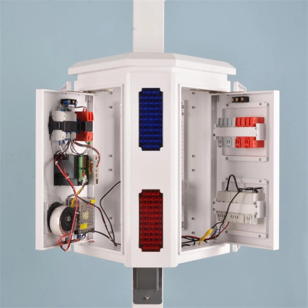
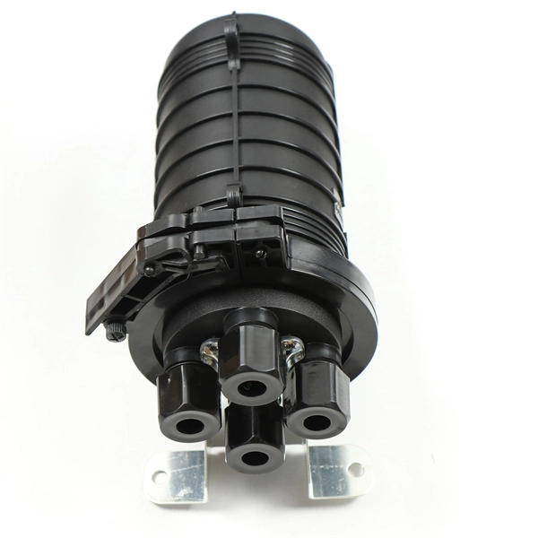
Distribution Box Ground Resistance Test
The selective testing method uses one clamp and two stakes. It allows you to measure the ground resistance at specific parts of an installation, isolating the system to check or reference what's in place. Th.
-
Optical cable OTDR curve test graph
This data represents information resulting from a test of fiber optic cable using an OTDR instrument, including distance, reflectance, loss, and fiber attenuation. You can view the data from up to four. Download free OTDR Trainer Software for PCs After you study this page, you can download a free OTDR Trainer to run on your PC. The Optical Time Domain Reflectometer (OTDR) is useful for testing the integrity of fiber optic cables. It can verify splice loss, measure length and find faults. To minimize testing time, compromises must be made on accuracy (detecting low loss. An OTDR allows you to locate splices, faults and breaks in optical fiber by analyzing backscattered light. Lets take the example below: This link has pretty much every type of event you nay expect to see.
-
Test Report on a New Vertical Cavity Surface Emitting Laser
Recent results on highly reliable 940nm multi-junction high power vertical-cavity surface-emitting lasers (VCSELs) are presented with target applications in depth sensing and Light Detection Ranging (LiDAR) markets. Vertical-cavity surface-emitting lasers (VCSELs) having a small aperture and operating in a single transverse mode (SM) are known to reach high relaxation oscillation frequencies of 30-90GHz and, thus, can offer intrinsic modulation bandwidth beyond 100GHz, once photon damping and electric. In this work, we present a high-performance vertical cavity surface emitting laser (VCSEL) based on a single-crystal CsPbBr 3 microplatelet, fabricated through a simple solution process and sandwiched between two distributed Bragg reflector (DBRs). Our innovation, the antireflective.