-
Grounding rectification measures for distribution boxes
First, we review and compare medium-voltage distribution-system grounding methods. Whether you're a seasoned pro or just starting out, this comprehensive guide will give you practical insights into proper grounding techniques, with a special focus on how selecting quality materials from a reliable building material supplier impacts your entire system's safety and longevity. Power from factory ground must be installed by a qualified electrician. We then analyze the behavior of ungrounded systems under ground fault. Ground rods are the most common grounding electrode found on distribution circuits. This chapter describes general grounding installation requirements for. An equipment grounding conductor passing through the box without a splice is not required to be joined inside the box to others that are spliced in the box.
-
How long should the grounding of the secondary distribution box be
The most common components of a GES are ground rods, which must be at least 8 feet in length and driven fully into the earth. If a single ground rod does not achieve a resistance to earth of 25 ohms or less, a second rod must be installed, separated from the first by a. A sub panel is a secondary distribution point that receives power from the main service panel, allowing for the extension of electrical service to a remote area of a building or a separate structure like a garage or shed. All grounding and bonding work must comply with NEC Article 250. Image used courtesy of Pixabay What Are Ground and Grounding? The. We earth ground systems to the earth to reduce overvoltage (from lightning induced energy and other events) on the conductors and electrical components (such as transformer and motor windings) of the installation. Grounding metal parts helps drain off static electricity charges before flashover. Learn the proper electrical grounding terminologies. Two levels of secondary voltage output define which.
[PDF Version]
-
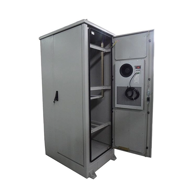
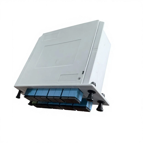
Grounding strip on the distribution box
Attach a ground wire from one of the threaded studs (A) at the bottom of the housing, to the mounting plate (B). The ground resistance between all system parts shall be <. Power from factory ground must be installed by a qualified electrician. Each DISTRIBUTION BOX and controller must be grounded. 26 mm 2 (10 AWG) ground wire must be used, and in all other markets a 6 mm 2 must be used. Grounding of the units: Attach a ground wire from one of. Whether you're a seasoned pro or just starting out, this comprehensive guide will give you practical insights into proper grounding techniques, with a special focus on how selecting quality materials from a reliable building material supplier impacts your entire system's safety and longevity. Choosing a reliable grounding bar is essential for sub panel safety and performance. Each product is evaluated on construction quality, screw count, compatibility, and durability. Check out our lowest priced option within Grounding Bars, the Bonding Screw by GE. Note: Product availability is real-time basis and adjusted continuously. It provides low electrical resistance.
[PDF Version]
-
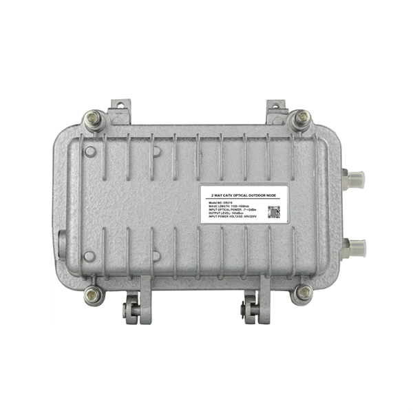
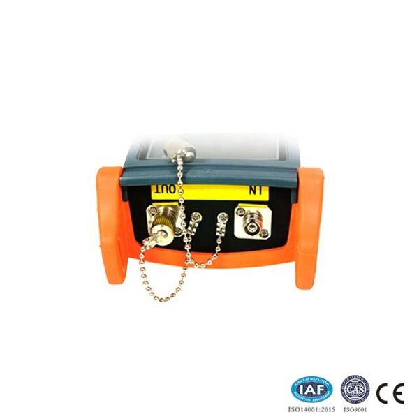
Fiber optic cable grounding in mobile communication equipment room
In installations where an optical fiber cable is exposed to contact with electric light or power conductors and the cable enters the building, the non–current-carrying metallic members shall be either grounded as specified in 770. 100, or interrupted by an insulating joint or. This Applications Engineering Note (AE Note) discusses conventional bonding and grounding practices for conductive fiber optic cable and hardware installations within the scope of the National Electrical Code (NEC). Systems include cables, messengers, and guys, or a combination of these facilities at the supply or communication level. The term “cable” means stranded conductor or a combination of conductors. Understanding fiber optic cable grounding requirements is essential for protecting your network infrastructure, preventing downtime and maintaining safety on the jobsite. Let's explore how fiber optic systems work, when grounding is required and how to do it correctly. Electric signs and metal equipment of outline lighting systems other than the portable and. The facility commenced operations in 2003, and its purpose was publicly revealed by AT&T technician Mark Klein in 2006.
[PDF Version]
-

Requirements for proper grounding of distribution boxes
26 mm 2 (10 AWG) ground wire must be used, and in all other markets a 6 mm 2 must be used. On the US market, a 5. If you're working with electrical systems, you know that grounding isn't just some bureaucratic requirement—it's literally the difference between a safe, functional system and a potential disaster. Today, we're diving deep into the world of distribution box grounding, breaking down the standards. Power from factory ground must be installed by a qualified electrician. This paper is intended to give an overview of the vari-ous relationships. Updated to current 2017 NEC, and included design manual requirement to include equipment grounding conductors in all feeder and branch circuits operating under 600 volts, and other editorial and typographic revisions.
-
Grounding Requirements for Cable Trays and Conduits
The NEC requirements for cable tray grounding are found in NEC Sections 392. 60(A) Marked as "Classified by U. 96 with bolted mechanical connectors or bonding jumpers. Cable tray may be used as the Equipment Grounding Conductor (EGC) in any installation where qualified persons will service the installed cable tray system. The metal in cable trays may be used as the EGC as per the limitations. It is essential that the grounding of cable tray systems, including the cables in the tray systems, is inspected for compliance with the grounding requirements in the National Electrical Code (NEC) BEFORE the cabling in the tray is energized and BEFORE cable is installed. If cable is installed. Grounding is one of the most critical NEC considerations when installing metallic cable trays. To comply with code requirements and ensure system safety, metallic trays must be electrically continuous, properly bonded at all splice points, and securely connected to the building's grounding system.
[PDF Version]
-
Fiber optic cable splicing techniques using heat shrink tubing
Carefully release each cable from splicer clamps. Slide shrink sleeve over exposed fiber and place in splicer's heating compartment; sleeve should cover each side roughly 3cm from joint. Consult the cable spec fication sheet for the cable you are installing. 1dB for fusion) and degrade over time in outdoor environments. A professional splice kit includes: Every splice starts with proper preparation: clean the work area, protect against wind, and. Single holed (preshrunk) ends eliminates improper fiber threading. Extended liner length prevents contact between the fiber and their backbone. Clear sleeve design permits easy centering. There are 7 procedures to perform in the splicing process; roughly in the following order: Procedures 2 and 3 will be performed twice; once for each of the two cables. Preparing to Use Heat Shrink Wrap: - Slide heat shrink wrap through one end of the fiber optic. A fiber optic heat shrink tube is used for reinforcing the splice connection.
[PDF Version]
-
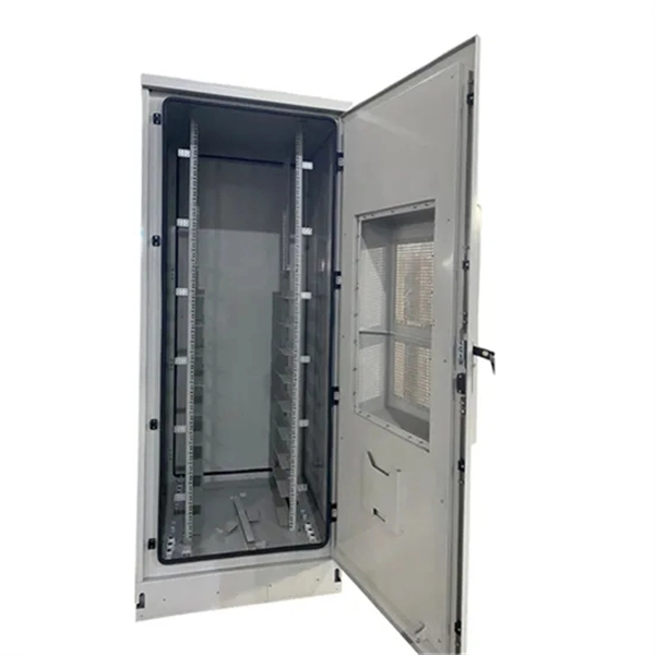
Wiring Techniques for Three-Level Distribution Boxes on Construction Sites
Check for proper IP/NEMA ratings and material quality. Ensure safe placement: install in dry, accessible areas with good ventilation and at appropriate height (typically ~1. Practice good wiring: secure grounding, neat cable management, proper insulation, and correct wire gauge. Learn how to wire a distribution box step by step! This video shows real on-site footage of electrical installation, demonstrating safe and standardized wiring methods used by professionals. The standard. Wiring methods. The provisions of this paragraph do not apply to conductors which form an integral part of equipment such as motors, controllers, motor control centers and like equipment. Metal raceways, cable armor, and. Wire color: The neutral wire is blue, and the color of the phase wire (A phase is yellow, B phase is green, and C phase is red) should meet the standard. However, exposure to weather, frequent relocation, rough use and other condi-tions not normally encountered with conventional wiring systems necessitate special consideration not require in other applications or in completed structures.
[PDF Version]
-
Equipotential bonding of distribution box
Equipotential bonding cables are required between two control cabinets with a minimum conductor cross-section of 16 mm². This protects people from electric shock and protects equipment or systems. Equipotential bonding (EPB) is a set of electric connections intended to achieve equipotentiality between conductive parts [Source: IEC 60050-195-2021]. The British Standard BS 7671 defines the term “equipotential bonding” as follows: Equipotential bonding is an electrical connection maintaining. “In each installation main protective bonding conductors complying with Chapter 54 shall connect to the main earthing terminal extraneous-conductive-parts including the following: (i) Water installation pipes (ii) Gas installation pipes (iii) Other installation pipework and ducting (iv) Central. Equipotential bonding is the foundation of a reliable lightning protection and surge mitigation strategy. 2020 Differences in potential between separated plant components can lead to high equalizing currents over the.
[PDF Version]
-
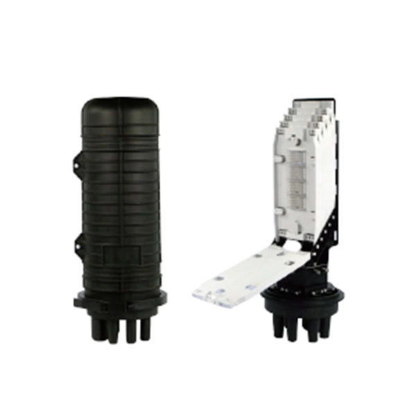
Lightning protection and grounding of mobile optical distribution boxes
This Recommendation provides guidance on protecting indoor distribution systems for mobile communication in large-scale buildings from lightning and safety risks. It emphasizes compliance with standards like IEC 62305-3, IEC 62305-4, IEC 60364 series, and ITU-T K. 21 for effective. We make safe, reliable and high-quality solutions for every spec and project. Lightning protection needs vary according to each specific facility. It is located at an elevation such that a line passing through the static wire and the outermost conductor below it is at a 30° aximum angle with a vertical line. ERICO® has complete telecommunications applications solutions to help protect the facility against electrical noise, lightning induced surges and transients caused by. Ground rods are the most common grounding electrode found on distribution circuits.
[PDF Version]
-
Reasons for switchgear busbar grounding
The ground bus inside metal-enclosed switchgear serves as more than a passive conductor. It determines whether personnel survive ground faults, whether protection relays operate correctly during switching transients, and whether equipment passes type testing. Grounding is one of the most crucial safety measures in electrical installations, and the bus bar. I know when you have a utilization voltage service transformer, you bond the neutral and ground buses at the service entrance equipment and from that point you are running 3P, 4W, plus an equipment ground through the whole system. The question I have is with primary switchgear used to distribute. This blog explains the difference between grounding in switchgear systems and earthing in switchgear system design, why they matter, and how they ensure reliable and safe power distribution. The neutral wire (white) and the equipment grounding conductor (EGC, bare or green) often terminate on bus bars that look. Abstract: System grounding considerations affect many aspects of an electrical system. Neutral and ground should only be connected together at one point in the electrical.
[PDF Version]