-
Installation steps for plastic cable trays
Step-1: Confirm the actual layout, dimensions & mounting height of cable trays & conduits. Step-3: Coordinate with other trades to prevent interference during installation. This guide breaks down the process step by step. Mark the cable tray route based on your electrical cable tray design and site. Article Summary: A compliant cable tray installation requires a thorough understanding of NEC Article 392, proper structural support, and precise installation techniques. In order to get it right, installers are supposed to adhere to a plan that ensures that wires are kept cool and the building is stable. The beginning of success is to review the Bill of Quantities (BOQ) so that. This method statement describes a detailed procedure for properly installing cable trays and conduits for the Feeder System. It ensures that all installation activities follow authorized plans, specifications, and standards.
[PDF Version]
-
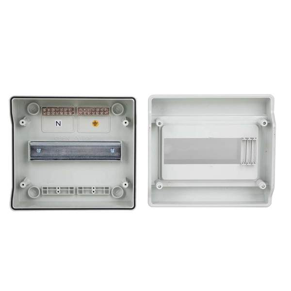
Function of the transformer in the secondary distribution box
Distribution transformers or secondary transformers, placed along feeders, convert the voltage from the medium to a low voltage level, suitable for direct consumption by end customers (mains voltage). The terms primary, secondary, and tertiary distribution boxes are relative. From the transformer's low-voltage side (0. 4kV), power is distributed to a main distribution panel. Primary distribution systems consist of feeders that deliver power from distribution substations to distribution transformers. Many feeders leave substation in a concrete ducts and are routed to a nearby pole.
-

Transformer distribution box grounding
This report is intended to be a primer that illustrates the fundamentals of neutral grounding and transformer winding configuration as they relate to distribution system protection. Grounding is a mechanism to protect distribution equipment and people under normal operating conditions, abnormal operational (overcurrent and overvoltage) responses, and hazardous conditions such as shocks. Grounding is necessary to assure correct operation of electrical devices, to assure safety. Grounding transformers is a deceptively simple task that carries significant implications for system safety and NEC compliance. During the data gathering process. IPMENT, STRUCTURES, ETC. IN ELECTRICAL STATIONS INCLUDING TRANSMISSION AND DISTRIBUTION SUBSTAT GR THAN 8 FT FROM THE FENCE. THE FENCE SHALL BE GROUNDED SEPARATELY FROM THE GRID UNLESS OTHERWISE NOTED ON THE A PROPRIATE PROJECT DRAWING. It improves safety, stability, and code compliance in power systems across utility and industrial settings.
[PDF Version]
-
What are hot-dip galvanized cable tray steps
Hot Dip Galvanized (GI) Ladder Cable Trays are metal trays with a ladder-like design, coated with a layer of zinc through the hot-dip galvanizing process. The ladder design features rungs that support and secure cables, allowing for easy installation, maintenance, and ventilation. The hot-dip galvanizing process involves several carefully controlled steps to ensure that cable trays receive the best possible protection against corrosion. From surface preparation to the final inspection, every stage is essential in achieving a uniform and durable zinc coating. There are. maintain spacing or to keep cables in place when the tray is ect the minimum bend ra-dius for cables as they exit the bottom of the cable tray.
-
Steps for Short Circuit Calculation in Relay Protection
Voltage levels, transformer ratings and impedances, line lengths and impedances, generator/motor data. Select fault location Choose busbars or nodes where faults will be studied. Apply IEC. A short circuit occurs when an unintended low-impedance path forms between: Physical Causes: Critical Applications: ⚠️ Safety Critical: Incorrect fault current calculations can result in explosive equipment failures, arc flash incidents causing severe burns, and system-wide cascading failures. The principle is to grade the operating times of the relays in such a way that. The scope of study involves calculating the settings for protective relays to achieve selectivity during faults ocurring in the electrical network for the 13. In OC relays the coordination is based on the relay time-current characteristics of instantaneous and/or time delay units. Instantaneous units should be set so they. As of this update, Service Disconnect Switches, Surge Protective Devices, Switchboards, Switchgear, and Panelboards, Industrial Control Panels, Motor Controllers, Elevators, Industrial Machinery, and Transfer Equipment are all required to have short-circuit current ratings.
[PDF Version]
-
Power Cable Tray Installation Steps
Step-1: Confirm the actual layout, dimensions & mounting height of cable trays & conduits. Step-3: Coordinate with other trades to prevent interference during installation. Article Summary: A compliant cable tray installation requires a thorough understanding of NEC Article 392, proper structural support, and precise installation techniques. The Cable Tray ng standards, performance standards, test standards and application in this document have been tested extens ompetent professional en completely installed, without damage either to conductors or. Here is a step-by-step guide on how to install a standard metal cable tray system (e. This guide covers copper and aluminum conductors from No. 14 AWG though 1000 kcmil, insulated for operation from 600 volts though 35 kilovolts.
-

Steps for laying out cable tray bends
This guide explains how to make 90° bends, vertical bends, tees, and offsets in wire mesh cable trays safely and professionally. Horizontal 90° Bend (Flat Bend) 2. But before you lay the first tray or clamp down a single cable, you need a solid plan. This guide breaks down the process step by step. When a wire cable tray is cut, the fact that a. Installing a cable tray system requires careful planning to ensure it can support the weight of the cables and adheres to electrical safety codes. Cable tray system design shall comply with National Electrical Code® (NEC® ) Article 392, NEMA VE 1, and NEMA FG 1 and follow safe work practices a described in NFPA 70E. Further, it is recommended that installers follow all guidelines and best practices found in NEMA VE 2. Students trading aid on how best to put an internal 90 degrees bend in steel cable tray.
[PDF Version]
-

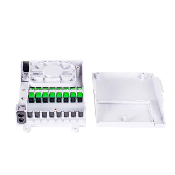
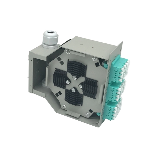
Fiber Optic Cable Splicing Process and Stitching Steps
Learn how to splice fiber optic cable using fusion splicing with this complete step-by-step guide. Includes tools, best practices, loss standards (ITU-T G. 652), cost analysis, and FAQs for network engineers and installers. Ensure Your Splicing Tools are Clean – #2. Before jumping into the physical steps, it's important to understand the two primary methods of fiber splicing: fusion splicing and. Splicing fiber optic cable is an extremely important phase for making dependable, high-speed communication infrastructures. more Learn how to splice fiber optic cable step by step in this complete guide! In this. Don't Miss this Super-Detailed Tutorial on Fiber Splicing and Winding! Don't Miss this Super-Detailed Tutorial on Fiber Splicing and Winding! The operation and skills of fiber optic fusion splicing technology can be mainly divided into five steps: fiber stripping, fiber cutting, fiber melting. Fiber optic cable splicing connects two cables, creating a strong link for fast data transmission. Splicing fiber helps light signals move easily, ensuring your internet connection remains reliable.
[PDF Version]
-
Distribution Box Branch Transformer
Distribution transformers consist of a magnetic core made from laminations of sheet silicon steel (transformer steel) stacked and either glued together with resin or banded together with steel straps, with the primary and secondary wire windings wrapped around them. This core construction is designed to reduce core losses and dissipation of magnetic energy as heat in the core, an econom. OverviewA distribution transformer or service transformer is a that provides a final reduction in the system, stepping down the voltage used in the distribution lines to the level used. Distribution transformers are classified into different categories based on factors such as: • Mounting location – pole, pad, underground vault• Type of insulation – liquid-imme. Distribution transformers are normally located at a, where wires run from a utility pole or underground power lines to a customer's premises. They are often used for the power supply of facilities outside sett.
[PDF Version]