-
Relay Protection Analysis and Application
Understanding of Power System Protection is critical for those concerned with power system relays. In this course, learn various protection schemes commonly used in electric utilities along with rea.
-
Analysis of the advantages and disadvantages of using multimode fiber
Multimode fiber has a larger core (typically 50 or 62. 5 microns) and can carry multiple light signals, usually LEDS, at once. While that's great for short distances, those overlapping signals can bump into each other and cause distortion over longer distances. There are two main types of fiber optic cables: single mode and multimode. That makes picking between single mode and multimode fiber optic cables an. Single mode fiber has a very narrow core (around 8–10 microns in diameter), so it only allows one light signal (or "mode") to pass through at a time. It has a narrow core diameter of 8-10 microns and uses a laser or. Whether data is being moved between facilities, connected to a data centre, or integrated into a broader communications system, the type of optical fiber in use has a direct impact on speed, reliability, and long-term scalability.
[PDF Version]
-
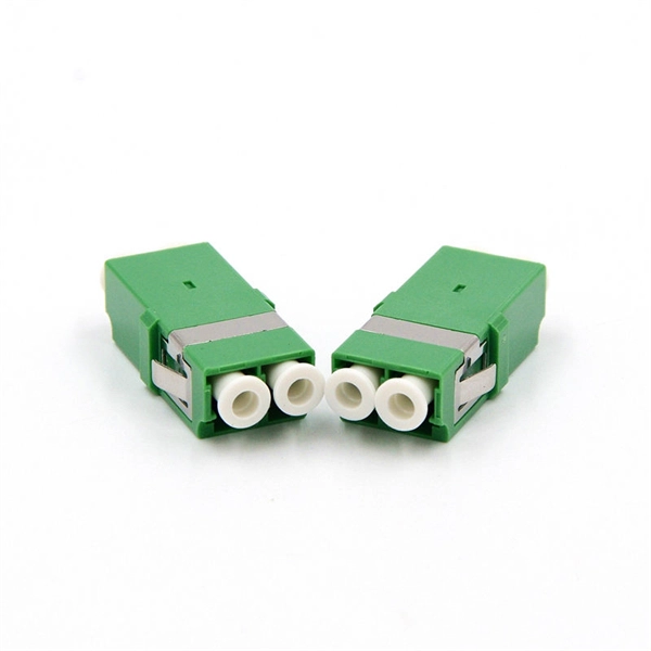
Performance of Optical Fiber Cable Fittings
Fiber coupling can be accomplished by fusion splicing. However, for temporary connections optical connectors are used to produce quick connections and disconnections. Fiber optic cables are essential components in modern data transmission infrastructure. They support high-speed, interference-resistant communication and are particularly effective in applications that require high bandwidth, low latency, and strong signal integrity. Combined with easy use, cleaning and maintenance. Tested for harsh and extreme environments (Norm IEC 61753-1 Cat. Dig-ups dominate! Cablers have very little influence on the majority of causes of cable field failures. While a small percentage, we can examine the “intrinsic” cable failures and what is done to prevent. Laboratory accelerated aging environments have long been used as a measure to predict field performance of optical fiber and cables' ability to withstand harsh environments. To this end, actual field.
[PDF Version]
-
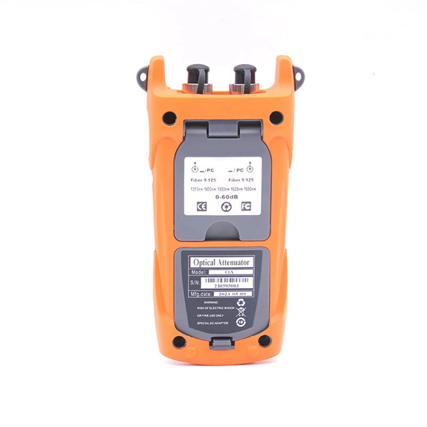
Analysis of the Causes of Attenuation in Fiber Optic Patch Cords
Fiber optic attenuation happens for two main reasons. Intrinsic losses come from the fiber's material and how light moves inside. Signal attenuation in fiber optics refers to the reduction in signal strength as it propagates through an optical fiber. The optical fiber material and the. Fiber optic cables have many advantages, but one of the downsides just like with copper cable, is that it can experience what is called attenuation. However, various factors can cause signal degradation, leading to performance issues and reduced network reliability. This can hurt your network, especially. To determine the power budget and power margin needed for fiber-optic connections, you need to understand how signal loss, attenuation, and dispersion affect transmission. Understanding it is crucial for anyone involved in data centers, telecommunications, or enterprise networking.
[PDF Version]
-
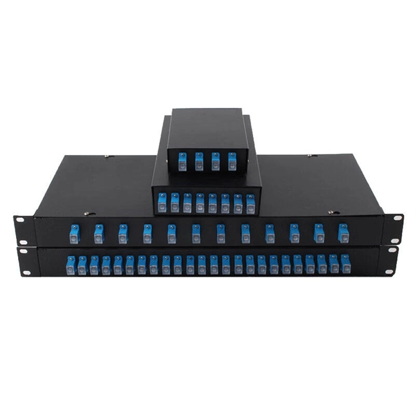
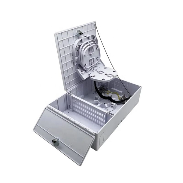
Analysis of the causes of signal attenuation in optical splitters
In the context of beam splitters, attenuation can occur due to several factors, including absorption, reflection, and scattering. Understanding how beam splitters affect signal attenuation and polarization is essential for optimizing systems in telecommunications, imaging, and laser applications. In the. Fiber optic splitters distribute optical power from one input fiber to multiple output fibers through either fused biconical taper (FBT) coupling or planar lightwave circuit (PLC) waveguide structures. Their performance depends on optical symmetry, waveguide integrity, and mechanical stability of. · Signal Attenuation: The loss of signal strength as it travels through the fiber can lead to poor quality communication. By careful processing, couplers that were bidirectional were made. So a 2:2 coupler would take the signal from one fiber on one side and split it between the two fibers on the.
[PDF Version]
-
Relay Protection Design Guidelines
This handbook covers the code of practice in protection circuitry including standard lead and device numbers, mode of connections at terminal strips, colour codes in multicore cables, dos and donts in execution. This document supplements PJM Manual 07 which contains the minimum design standards and requirements for the protection systems associated with the bulk power facilities within PJM. The IEC standard for relay coordination provides clear guidelines and methodologies to ensure that protective relays work in harmony to isolate only the faulty section of the system while keeping the rest. Protective relays and devices have been developed over 100 years ago to provide “last line” of defense for the electrical systems.
-
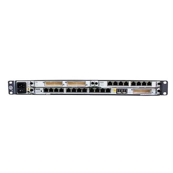
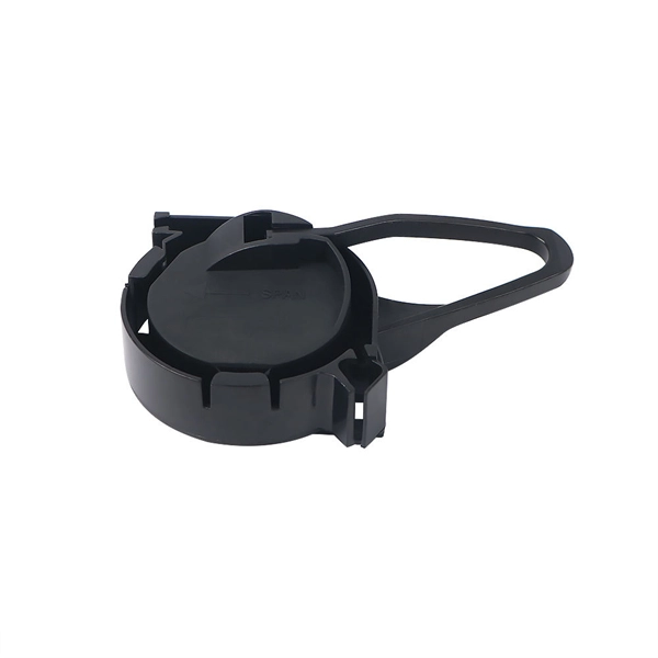
Optical Module Base Design
Optical module usually consists of a transmitter assembly (TOSA, containing a laser LD chip), a receiver assembly (ROSA, containing a photodetector PD chip), a driver circuit, an optoelectronic interface, a heat sink (some models), a housing, a pull ring and so on. Integrated circuits and reference designs help you create a smaller and faster optical module design used in high-bandwidth data communication applications. Whether you are creating a 100-Gbps or 400-Gbps, small form-factor pluggable (SFP) module, SFP+ transceiver, XFP module, CFP, X2/XENPAK module. Designing and producing these complex PCBs presents formidable challenges, requiring a convergence of disciplines—from high-frequency signal integrity and advanced thermal management to micron-level mechanical precision. These three laser diodes are described in more detail. contact us product page Copyright © 2024 MVSLINK. Critical Metrics: Signal integrity (insertion loss, return loss) and thermal management are the two.
[PDF Version]
-
Performance of ordinary optical fiber cables for communication
Fiber optic cables are essential components in modern data transmission infrastructure. They support high-speed, interference-resistant communication and are particularly effective in applications that require high bandwidth, low latency, and strong signal integrity. It traces OFC's. is this technology that provides homes and businesses with fiber-optic internet, phone and TV services. Charles Kuen Kao is known as the “father of fiber optic communications” for his discovery in the 1960s of certain physical roperties of glass, which laid the groundwork for high-speed data. Abstract—The development of optical fiber has compared to earlier copper cables.
-
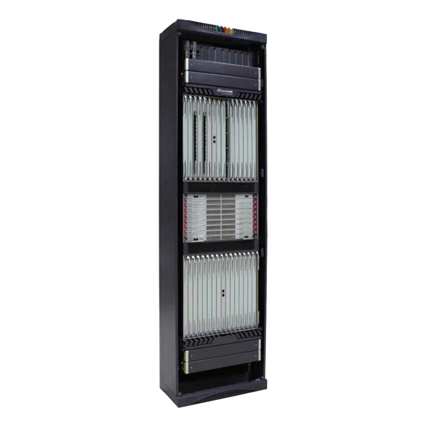
Principles and Product Design of Optical Fiber Communication
Optical Fiber Communication (OFC) revolutionizes modern telecommunications, enabling rapid data transfer across long distances with minimal signal loss. This comprehensive review explores OFC's historical evolution, core principles, components, and versatile applications. Kanade Department of Electronic-Science, P. College of ASC, Pravaranagar, India fPublished. The digital communication techniques discussed so far have led to the advancement in the study of both Optical and Satellite communications. Light acts as a carrier wave and can be modulated to carry information. Higher bandwidth (extremely high data transfer rate).
-

WDM Fiber Optic Communication System Design
This lesson demonstrates the basic features of a typical WDM optical communication system and shows the basic design steps with OptiSystem. The performance of the system will be shown and compared. In fiber-optic communications, wavelength-division multiplexing (WDM) is a technology which multiplexes a number of optical carrier signals onto a single optical fiber by using different wavelengths (i. Single mode fiber is favored over Multimode fiber for long-distance communication. Firstly, the WDM optical. While fiberoptic technology resulted in a significant increase in a network's "bandwidth," or the amount of information that the network could send, tbe creation of the Internet resulted in an even greater demand for bandwidth. As demand for network capacity increased, service providers exhausted.
-
Requirements for Relay Protection Design
The IEEE standard for protection relays refers to a collection of guidelines developed by the Institute of Electrical and Electronics Engineers. This document provides recommendations, background and philosophy on relay protection that is not available in M07. They are intended to quickly identify a fault and isolate it so the balance of the system continue to run under normal conditions. For professionals working in utilities, industries, or renewable energy systems, understanding these standards is not optional—it is essential. This handbook covers the code of practice in protection circuitry including standard lead and device numbers, mode of connections at terminal strips, colour codes in multicore cables, dos and donts in execution.
-
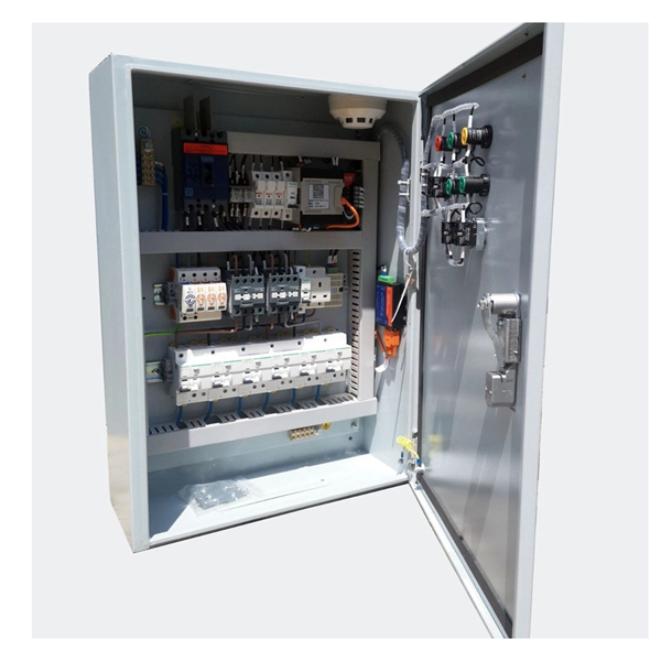
Emergency Circuit Design for Distribution Boxes
Size emergency and standby circuits with NEC 700/701, IEC 60364-5-56, UPS/generator transfer paths, and real voltage-drop examples. On a recent plan review, the riser looked clean: NEC 700 emergency lighting, a listed transfer switch, copper conductors, and breakers sized. Emergency and standby power systems are designed to provide an alternate source of power if the normal source of power, typically the electric utility service, should fail. Reliability of these types of systems is critical and good design practices are essential. Classification of Emergency and. Emergency system circuits supply power to critical life safety loads such as emergency lighting, fire alarm systems, fire pumps, smoke control systems, and essential communication and control circuits. Correct wiring design for emergency system circuits is essential to maintain power integrity. The National Electrical Code (NEC) Section 700. Under no. Another is to limit what qualifies as an “emergency load,” so the emergency system powers only what is needed to save human life (Fig.
[PDF Version]