-

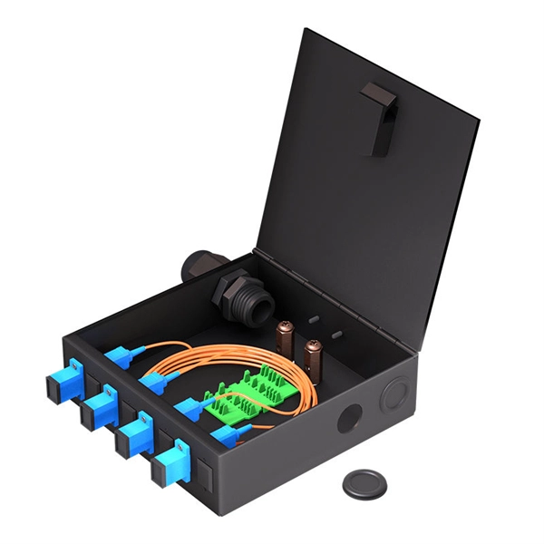
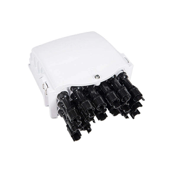
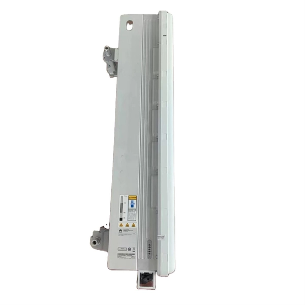
Function of rack-mounted optical amplifier splitter
Designed to house multiple fiber splitters in a single rack unit, these devices simplify signal routing and help keep your network structured — without sacrificing valuable space. Rack-mount fiber optic splitters are passive optical splitters integrated into standard rack-mounted chassis, typically installed in telecom racks, ODF frames, or central office distribution systems. Unlike compact module splitters placed inside terminal boxes, rack-mount splitters are designed for. VOYGAR provides ABS Cassette PLC Splitter family has 1x2, 1x4, 1x8, 1x16, 1x32, 1x64, 2x2, 2x4, 2x8, 2x16, 2x32,2 x 64 PLC splitter, with specifications that are tailored for different applications and markets. The structure of rack chassis PLC splitter is to install. Fiber Optic PLC Splitter is an essential passive component in Fiber to the Home network.
-
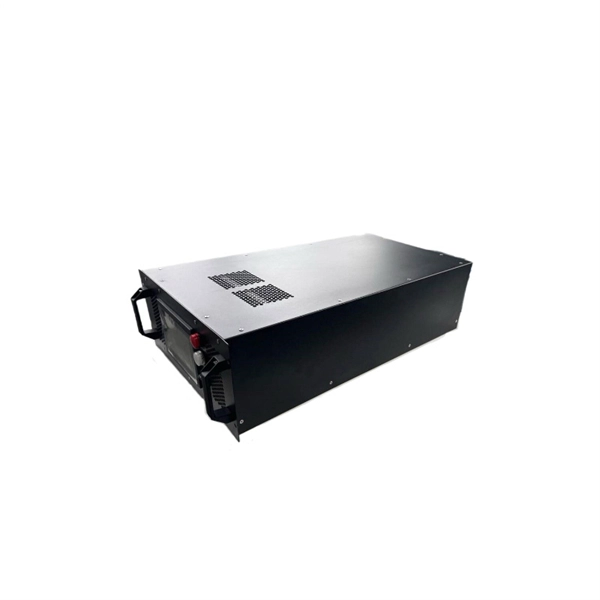
The function of a 10 Gigabit optical splitter
By dividing a single optical signal from a central Optical Line Terminal (OLT) into multiple outputs for Optical Network Terminals (ONTs) at users' homes, splitters eliminate the need for dedicated fibers to each residence—slashing infrastructure costs while scaling network reach. An Optical Splitter, also known as a beam splitter, is a passive optical device that divides a single input optical signal into two or more output signals. Conversely, it can also combine multiple signals into one. Optical splitter. Where splitters are placed in the network can make significant impacts on fiber counts, network cost and deployment time and operational steps, such as customer onboarding and maintenance. One important note is that splitting architectures should be seen as tools that can be mixed and matched to. The trick is how that single signal gets divided. That's where splitters come in.
[PDF Version]
-
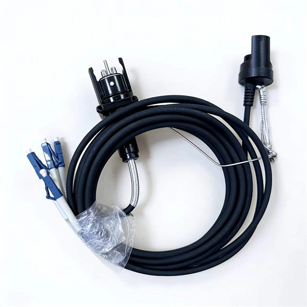
Method for bundling optical cables
Fiber optic splicing is often the preferred way to connect two fiber optic cables because it has lower light loss (attenuation) and back reflection than connectorization. Fusion splicing and mechanical splicing are the two most common methods of fiber optic splicing. AOCsarrive. This document describes the specifications for preparing, routing, and bundling cables and attaching labels to these cables. Another method of connecting optical fibers is termination or connectorization, which consists of processing the end of a fiber optic bundle so that it can be connected to other fibers or devices through fiber optic. In the rapidly evolving fields of telecommunications, medical imaging, and industrial sensing, fiber optic bundles serve as the cornerstone for efficient and reliable data transmission.
-
Qatar Optical Cable Silicon Core Tube Brand
Fibre Optic Cables and Accessories have taken the networking and telecom domain in their stride and offer one of the most popular and reliable means to communicate and share data. Electra is a leadin.
-
Egypt Solution ONU Optical Network Unit PAM4
A physical-layer network coding (PNC) based inter-ONU-communication (IOC) scheme is proposed for next generation high-speed PONs which apply four-level pulse amplitude modulation (PAM4). A 25 Gb/s f.
-
Direct Sales of Gigabit Optical Modules from Manufacturers in Mali
U.S. exporters should identify a local agent or distributor to assist in bringing goods to market in Mali. Businesses should be aware, however, that entering a successful partnership or representational relatio.
-
Optical Ground of Fiber Optic Communication Line
OPGW (Optical Ground Wire) is a kind of cable that comprises the dual functions of grounding and fiber optic communication. It is increasingly utilized in high-voltage transmission lines as a functional element that both safeguards the power system and allows data sharing across the. An optical ground wire (also known as an OPGW or, in the IEEE standard, an optical fiber composite overhead ground wire) is a type of cable that is used in overhead power lines. Widely used in overhead transmission lines, OPGW plays a crucial role in modern smart grids, telecom integration, and utility infrastructure.
-
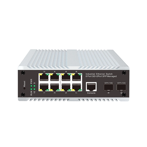
Which port on the switch is the optical interface
The optical port of an industrial Ethernet switch refers to the optical fiber interface, which has single-mode, multi-mode, gigabit, and gigabit specifications. Port types are limited to two: optical and Ethernet. RJ45 ports serve access-layer copper connections; SFP/SFP+ ports enable flexible 1G/10G uplinks; SFP28 delivers 25G for modern data centers; QSFP+ and QSFP28 support high-density 40G/100G spine–leaf. GBIC is an interface device that converts gigabit electrical signals into optical signals. This design enables end-to-end optical signal transmission, avoiding the conversion between electrical and. The optical ports on the switch are usually paired together, with one TX sender and one RX receiver. The. Most SFP fiber optic modules use LC connectors, while SC connectors are mainly found in legacy networks and MPO/MTP connectors are used for high-density cabling rather than directly on standard SFP modules. This connector landscape reflects how modern SFP deployments prioritize port density and.
[PDF Version]
-
Does the FC interface transmit optical or electrical signals
The FC-0 specification includes cables, connectors, and optical and electrical parameters for a variety of data rates. This connector landscape reflects how modern SFP deployments prioritize port density and. Physical Fibre Channel (FC) is a high-speed data transfer protocol providing in-order, lossless delivery of raw block data. Fibre Channel is primarily used to connect computer data storage to servers in storage area networks (SAN) in commercial data centers. Host Bus Adapter (HBA) An HBA is a dedicated hardware component that connects a server to a Fibre Channel storage. Traditionally, compute operating systems have communicated with peripheral devices over channel connections, such as Enterprise Systems Connection (ESCON) and SCSI. Channel technologies provide high levels of performance with low protocol overheads. The connector mechanically orients the fiber cores, allowing light to pass and travel through.
[PDF Version]
-
10 Gigabit Ethernet card optical module not connected to fiber optic cable
Troubleshooting SFP+ link issues in 10 GbE networks requires attention to module type, match of speed and wavelength, clean fiber connections, correct configuration, thermal management, and equipment compatibility. You can quickly resolve SFP+ Module connectivity issues by following a systematic optical transceivers troubleshooting process. Check for common connection problems, such as link failures or modules not recognized. Check compatibility between the optical module and switch Most switch brands have specific compatibility requirements. During network upgrades, many enterprise users encounter a common issue: after replacing 10G broadband lines or inserting 10G SFP+ optical modules, the switch still fails to operate at full 10G bandwidth or even fails to recognize the modules. We've listed the five most common ones. First of all, let's briefly recap what SFP and SFP+ stand for. SFPs – short for 'small form-factor pluggable' – are compact, hot-pluggable devices.
[PDF Version]
-
Hazards of Laying Optical Cables
Optical fibers, though renowned for their efficiency and bandwidth, aren't immune to risk factors that could spawn safety hazards. The very nature of fiber optic cabling requires handling microscopic strands that, when damaged, can cause signal loss or, worse, physical harm. Understanding the safety hazards that go with fiber optic cable is critical for those who install or maintain fiber optic systems. As electrical professionals, most of us take fiber optic (FO) safety for granted. Recognizing the potential safety hazard inherent in the installation and maintenance of optical fibers is crucial to mitigating risks of personal or property damage. Know the standards that apply to your work Whether you're installing new fiber optic cables or troubleshooting and repairing an existing fiber network, a working knowledge of the regulations that apply to your. However, fiber optics installation is not without risks. Even the output of OTDRs, WDM and fiber amplifier systems, which are. Working with fiber optic cabling requires precision, skill, and a strong understanding of cabling safety.
[PDF Version]
-

Switches are all 10 Gigabit optical
To implement different 10GbE physical layer standards, many interfaces consist of a standard socket into which different physical (PHY) layer modules may be plugged. PHY modules are not specified in an official standards body but by (MSAs) that can be negotiated more quickly. Relevant MSAs for 10GbE include (and related X2 and XPAK), and. When choosing a PHY.