-
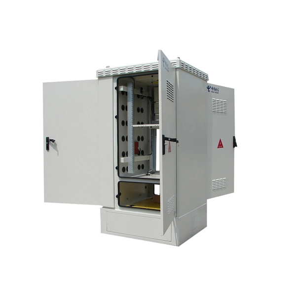
Cables are run through busbars and cable trays
A bus duct (busway system) is a prefabricated power distribution system that uses solid copper or aluminum busbars enclosed in a protective housing. Busbar systems are often preferred over cables because they save space, install faster, offer greater flexibility for changes, and provide enhanced reliability, frequently leading to a lower total cost of ownership. These conductors are usually copper or aluminum. vides a comparison between cable tray and cable bus for power distribution systems. The comparison includes various eneral considerations on both products, highlighting pros and cons of both systems. A cable tray system provides structural support for various types of cables, ensuring they are securely mounted and organized. What Is a Busbar? A busbar.
-
How to calculate the support structure for steel cable trays
Cable tray support quantity can be calculated using a simple formula: Support Quantity = Total Length ÷ Support Spacing + 1 20 ÷ 2 + 1 = 11 supports In a typical project, a 20-meter cable tray with 2-meter spacing requires 11 supports. As a key structure supporting the cable tray, the accurate calculation of the support quantity directly affects construction costs, efficiency, and safety. In complex engineering environments, the. This guide covers the critical steps, from selecting the right electrical cable tray and performing accurate cable fill calculations to managing a safe cable pull through and ensuring all bonding and grounding requirements are met. Ideal for electrical contractors and engineers. Classification of Loads Cable tray loads can be classified into the following categories: Dead Load (G): This. Correct sizing prevents sagging, overheating, and premature failure. You don't need a PhD—just a consistent method. This step‑by‑step approach helps you determine width, depth, support spacing, and allowable load with confidence.
[PDF Version]
-

The role of cable trays in cable laying and installation
When properly selected and installed, cable trays simplify routing, improve accessibility, and support future expansion while maintaining compliance with electrical codes and standards. How about organizing your wiring with a cable tray system? Smart move. But before you lay the first tray or clamp down a single cable. Article Summary: A compliant cable tray installation requires a thorough understanding of NEC Article 392, proper structural support, and precise installation techniques.
-
Can cable trays be blocked
Barriers are designed to separate and protect cables within trays, preventing potential damage from external forces or accidental contact. The cable tray is about 2-feet wide and the sprinklers are standard uprights. However, the cable tray may be centered directly below some. Recognize electrical cable tray misuse that can lead to electric shock and arc-flash/blast events and fires caused by overheating. The most common hazards include: 👉 If ignored, these risks can lead to equipment failure, fire, or even fatal accidents Working with cable trays is not just a routine installation job. 6 (E) seems to allow it, "Multi-conductor cables rated 600V or less shall be permitted to be installed in the same cable tray. 9 (A) (2), which describes the condition we found.
-
1-meter wide cable tray support spacing
Generally, standard trays require supports every 6 to 10 feet, while heavy-duty, long-span trays can handle distances of up to 20 feet between supports. To determine the proper spacing, consult the manufacturer's load capacity chart, which accounts for the total weight of the. The NEC requires that cable trays must be supported by members at an interval specified by the cable tray manufacturer, but not more than 5 feet for horizontal runs to support the weight of the cables and other loads. The NEC has a requirement for ladder-type cable trays. The rungs cannot be more. en completely installed, without damage either to conductors or structural system use maintain spacing or to keep cables in place when the tray is ect the minimum bend ra-dius for cables as they exit the bottom of the cable tray. Proper installation can significantly reduce electromagnetic interference, prevent fire hazards, and improve overall efficiency. This article provides an in-depth. Ladder cable tray is available in widths of 6, 9, 12, 18, 24, 30, 36, 42 and 48 inches with rung spacings of 6, 9, 12 or 18 inches. The Ladder Tray features light, rugged, tubular steel construction.
[PDF Version]