-
1-meter wide cable tray support spacing
Generally, standard trays require supports every 6 to 10 feet, while heavy-duty, long-span trays can handle distances of up to 20 feet between supports. To determine the proper spacing, consult the manufacturer's load capacity chart, which accounts for the total weight of the. The NEC requires that cable trays must be supported by members at an interval specified by the cable tray manufacturer, but not more than 5 feet for horizontal runs to support the weight of the cables and other loads. The NEC has a requirement for ladder-type cable trays. The rungs cannot be more. en completely installed, without damage either to conductors or structural system use maintain spacing or to keep cables in place when the tray is ect the minimum bend ra-dius for cables as they exit the bottom of the cable tray. Proper installation can significantly reduce electromagnetic interference, prevent fire hazards, and improve overall efficiency. This article provides an in-depth. Ladder cable tray is available in widths of 6, 9, 12, 18, 24, 30, 36, 42 and 48 inches with rung spacings of 6, 9, 12 or 18 inches. The Ladder Tray features light, rugged, tubular steel construction.
[PDF Version]
-
How far apart should the cable tray be placed with its fixed support
Support spacing for cable trays must align with the manufacturer's instructions, as outlined in NEC 392. Generally, standard trays require supports every 6 to 10 feet, while heavy-duty, long-span trays can handle distances of up to 20 feet between supports. The NEC has a requirement for ladder-type cable trays. This is a description of how to select, install, and support these metal or plastic frames, on which electrical wires are installed. You should consider it as a series of instructions that make the buildings resistant to. When installing two cable trays in parallel at the same height, the distance between them should be no less than 0. But it's also important to minimize.
-
How much distance should the cable tray support be installed
Generally, standard trays require supports every 6 to 10 feet, while heavy-duty, long-span trays can handle distances of up to 20 feet between supports. To determine the proper spacing, consult the manufacturer's load capacity chart, which accounts for the total weight of the. The NEC requires that cable trays must be supported by members at an interval specified by the cable tray manufacturer, but not more than 5 feet for horizontal runs to support the weight of the cables and other loads. The NEC has a requirement for ladder-type cable trays. This spacing is crucial for adequate maintenance access, ease of inspection, and ensuring proper airflow for effective heat dissipation. Support Methods: Common support methods include trapeze hangers, which are. This is a description of how to select, install, and support these metal or plastic frames, on which electrical wires are installed.
[PDF Version]
-
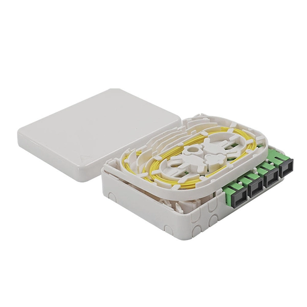
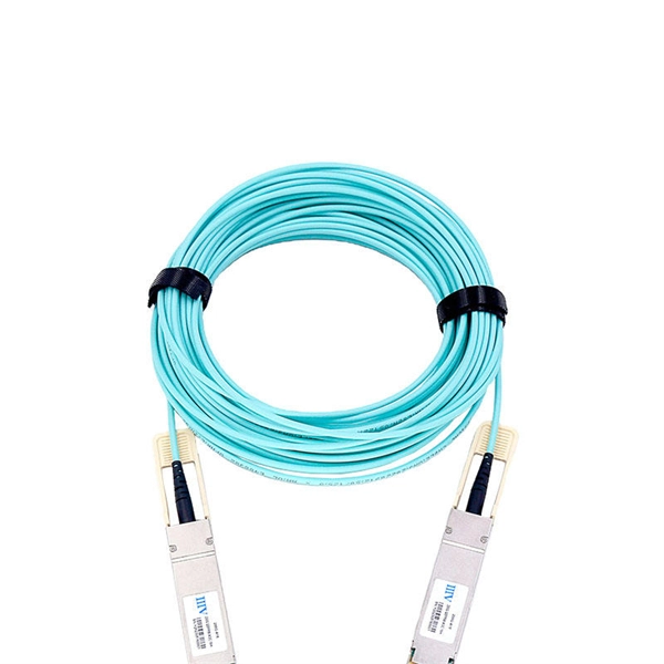
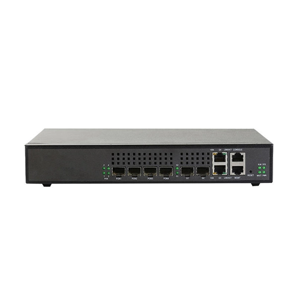
How many cascading levels does a fiber optic switch support
The switch connected to the switch is called cascade. However, in the actual application process, it is recommended that the cascade does not exceed four layers. Cascading can be defined as two or more switches. This guide focuses on two critical aspects of optical splitters that define FTTH performance: split ratios (how signals are divided) and splitting architectures (how splitters are deployed). A key challenge is determining how many users a single OLT port can support, which is defined by the split ratio. Traditional GPON networks often employ 1:32 or 1:64 splits. The connection between two or more Ethernet switches in a certain way (Uplink port, etc. Multiple switches can be cascaded in various ways according to. On the other side of the splitter, 32 fibers are routed through distribution panels, splice ports and/or access point connectors to 32 customers' homes, where it is connected to an optical network terminal (ONT).
[PDF Version]
-
Classification of Generator Relay Protection Properties
Generator Protections are broadly classified into three types: Class A, B and C. Class A covers all electrical protections for faults within the generating unit in which generator field breaker, generator breake.
-
Elevator cable tray support spacing
Support spacing for cable trays must align with the manufacturer's instructions, as outlined in NEC 392. Generally, standard trays require supports every 6 to 10 feet, while heavy-duty, long-span trays can handle distances of up to 20 feet between supports. Specifiers should be aware that some cable tray. Understanding cable tray spacing is key to meeting safety regulations and maintaining system performance. The spacing between trays, whether horizontal or vertical, depends on various factors like cable type, environment, and tray material. The Ladder Tray features light, rugged, tubular steel construction. 50 in the development and approval of the document at the time it was developed.
-
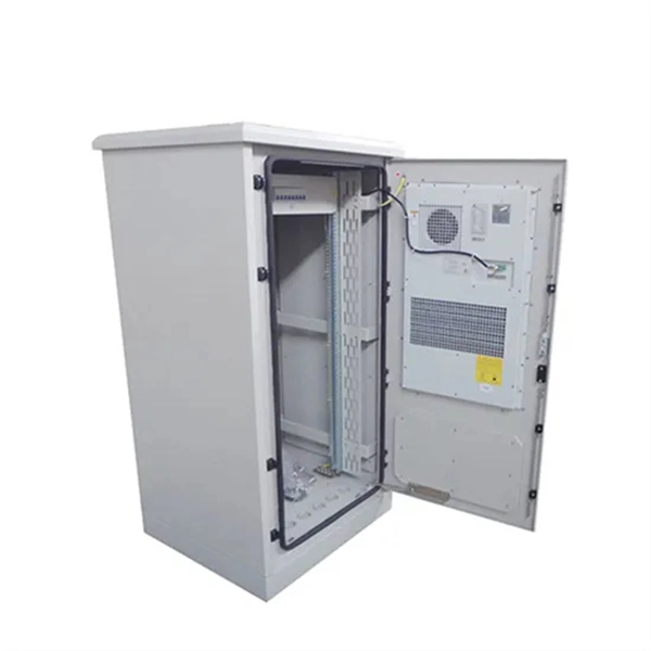
Generator Distribution Box Configuration
In this guide, we'll break down everything you need to know to install a distribution box correctly and confidently. Choose the right box based on environment (indoor/outdoor), load capacity, and durability. Check for proper IP/NEMA ratings and material quality. To safely and efficiently distribute power from a portable generator, a portable generator connection box is an essential accessory. Single-phase units are suited for smaller applications, while three-phase units handle larger loads, making them ideal for construction. The Generator Connection Cabinet (GCC) provides a connection point only for a portable generator or load bank. A consulting electrical engineer can help determine the optimal configuration to. NFPA 70: National Electrical Code Article 700 specifies the requirements to install emergency power systems such as lighting when power from the normal source is interrupted. Ensure safe placement: install in.
[PDF Version]
-
Revit cable tray material change
Use the Object Styles command to set global material setting for Cable Trays Add view filters for the different cable trays to adjust the lines/patterns/transparency values. When trying to select a material for cable trays in Revit, the material parameter does not appear in the properties of the instance and type properties of cable trays: Currently in Revit, there is no material parameter in the cable tray type properties dialog. But filters don't carry through to IFC exports. To solve this, we need to generate materials based on. We can apply cable tray material in MANAGE>OBJECT STYLES>CABLE TRAY & CABLE TRAY FITTING (For all types). I know I can change the rung dimensions alright but the side rails. However, the issue I am facing now is all cable tray segments are applied with same perforated material. In the attached pic, I want to.
[PDF Version]
-
Are ladder racks used as support frames for cable trays
Ladder rack (also known as “ladder trays” or “cable ladders”) are one of the most common types of cable runway. As the name suggests, they're constructed of two side rails connected by rungs, creating an open structure for cable support and management. Whether suspended from the ceiling, wall-mounted, or supported by racks and cabinets, overhead cable management systems are flexible and scalable. They can easily be moved, reconfigured, or expanded as needed to meet changing requirements and evolving connectivity needs.