-
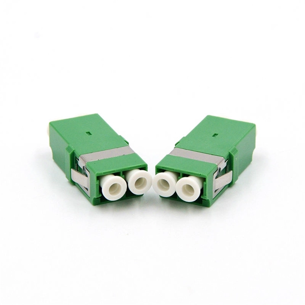
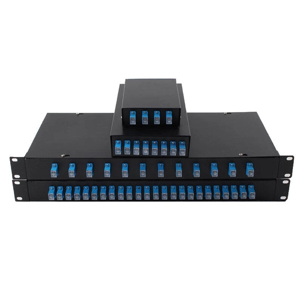
Analysis of the causes of signal attenuation in optical splitters
In the context of beam splitters, attenuation can occur due to several factors, including absorption, reflection, and scattering. Understanding how beam splitters affect signal attenuation and polarization is essential for optimizing systems in telecommunications, imaging, and laser applications. In the. Fiber optic splitters distribute optical power from one input fiber to multiple output fibers through either fused biconical taper (FBT) coupling or planar lightwave circuit (PLC) waveguide structures. Their performance depends on optical symmetry, waveguide integrity, and mechanical stability of. · Signal Attenuation: The loss of signal strength as it travels through the fiber can lead to poor quality communication. By careful processing, couplers that were bidirectional were made. So a 2:2 coupler would take the signal from one fiber on one side and split it between the two fibers on the.
[PDF Version]
-
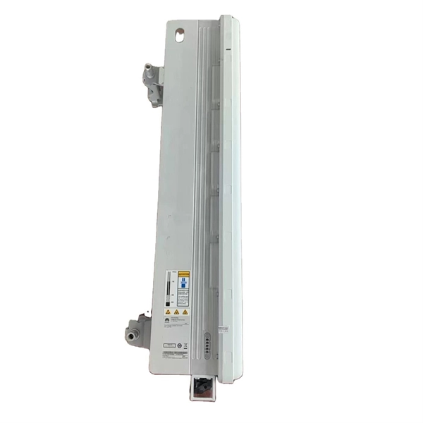
Analysis of Optical Module Sensitivity Issues
This guide provides a comprehensive overview of sensitivity analysis in optical design. It involves analyzing how the performance of an optical system varies in response to changes in its design parameters. For example, SONET specifies that the BER must be 10 -10 or better. By understanding the measurement standards, influencing factors, and application. It is often useful to analyze your tolerances in detail so that you can best understand where and why sensitivities exist in your optical system. In OpticStudio's tolerance analysis, you may save the tolerance results for each Monte Carlo file, or you may save each tolerance in the sensitivity.
-
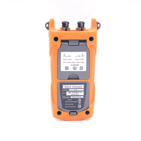
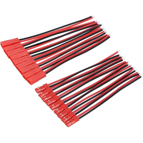
Analysis of the Causes of Attenuation in Fiber Optic Patch Cords
Fiber optic attenuation happens for two main reasons. Intrinsic losses come from the fiber's material and how light moves inside. Signal attenuation in fiber optics refers to the reduction in signal strength as it propagates through an optical fiber. The optical fiber material and the. Fiber optic cables have many advantages, but one of the downsides just like with copper cable, is that it can experience what is called attenuation. However, various factors can cause signal degradation, leading to performance issues and reduced network reliability. This can hurt your network, especially. To determine the power budget and power margin needed for fiber-optic connections, you need to understand how signal loss, attenuation, and dispersion affect transmission. Understanding it is crucial for anyone involved in data centers, telecommunications, or enterprise networking.
[PDF Version]
-
Analysis of the advantages and disadvantages of using multimode fiber
Multimode fiber has a larger core (typically 50 or 62. 5 microns) and can carry multiple light signals, usually LEDS, at once. While that's great for short distances, those overlapping signals can bump into each other and cause distortion over longer distances. There are two main types of fiber optic cables: single mode and multimode. That makes picking between single mode and multimode fiber optic cables an. Single mode fiber has a very narrow core (around 8–10 microns in diameter), so it only allows one light signal (or "mode") to pass through at a time. It has a narrow core diameter of 8-10 microns and uses a laser or. Whether data is being moved between facilities, connected to a data centre, or integrated into a broader communications system, the type of optical fiber in use has a direct impact on speed, reliability, and long-term scalability.
[PDF Version]
-
Relay Protection Analysis and Application
Understanding of Power System Protection is critical for those concerned with power system relays. In this course, learn various protection schemes commonly used in electric utilities along with rea.
-
Silicon-Iron Elemental Composition Spectrometer
SVDV-ICP-OES is a technique used for the detection of elements at trace (parts of million) levels in numerous sample types, which provides a highly reliable technique due to good stability, limited spectral interferences and low matrix effects. The recent advances in EDS performance with the silicon drift detector (SDD) enable. Our robust family of Thermo Scientific ARL XRF spectrometers provides fast, repeatable elemental analysis measurements with little to no sample preparation. Advanced models — such as the SPECTRO xSORT handheld XRF spectrometer from SPECTRO Analytical Instruments — produce fast, accurate results on the spot, for sample identification, gra e sorting, and metals analysis. Energy Dispersive Spectroscopy, also knows as EDS or EDX, and sometimes even as EDAX is a non-destrutive way to get the elemental composition of an element. The system is very affordable with high reliable and quality. It delivers high sensitivity, a wide dynamic range and strong tolerance for complex matrices, making it ideal for pharmaceutical and food.
[PDF Version]
-
Should grounding flat iron be placed in cable trays
Where cable tray systems contain only signal and communication circuits that operate at low energy levels, power grounding per NEC Section 318-7 is not appropriate, but cable tray grounding for lightning protection, noise, and electromagnetic interference is necessary. Cable tray may be used as the Equipment Grounding Conductor (EGC) in any installation where qualified persons will service the installed cable tray system. 8, 11, and 12, and the National Electrical Code Sections 318-3-© and 318-7. It is also covered in NEMA Standard VE-2. The purpose of power grounding (Article 250) is to minimize the damage from wiring or. Grounding and bonding are mandatory for metallic trays. Tray fill limits must be calculated properly. Power and data cables require proper separation.