-
Main protective measures for optical cables
Maintain accurate as-built drawings and GPS coordinates for all buried cable routes. This prevents accidental cuts during future excavation. Cable protection extends beyond the fiber itself—connectors, splices, and enclosures must be safeguarded from environmental and mechanical. Fiber optic cables enable high-speed, long-distance data transfer, forming the backbone of modern communication. This guide covers how to. es conform to the guidelines expressed in the American National Standards Institute document (ANSI Z535) for hazard alert messages. Alerts are included in this instru d ath or serious i jury ectacles) conforming to ANSI Z87, for eye protection from accidental injury wh n ha dling chemicals, cab. Improper use of the connector end face on pigtailed fibers, e. Use of inferior quality fiber optic connectors. ESD damage is a major issue that can degrade the. It is important for fiber optic technicians to follow safety practices to avoid injuries and accidents.
[PDF Version]
-
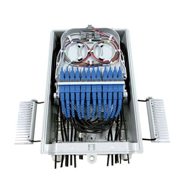
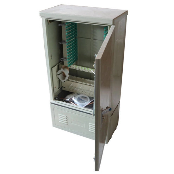
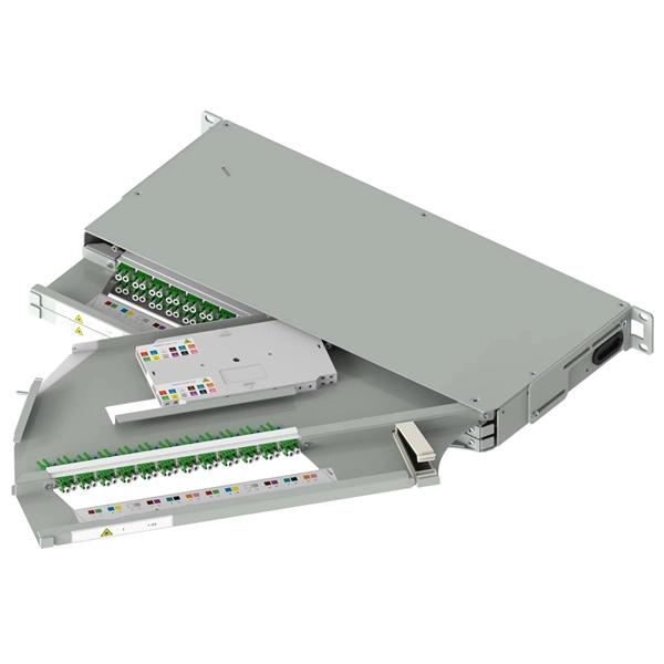
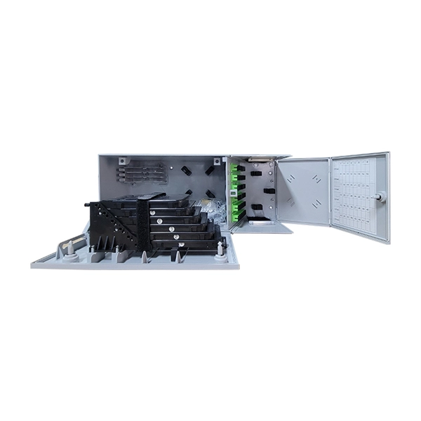
What are the main components of an optical distribution box
ODF, also known as optical distribution frame or fiber optic patch panel, is a critical device used in optical communication for managing and distributing optical fibers. They provide efficient fiber optic management, connectivity, and protection. It is usually a compact and structured framework composed of a steel shell and internal fiber splice tray as the main. This complete guide explores everything you need to know about ODFs — from their structure, types, and key components, to installation best practices and modern design trends. Whether you're building a central office, data center, or FTTx distribution network, understanding the right ODF.
-
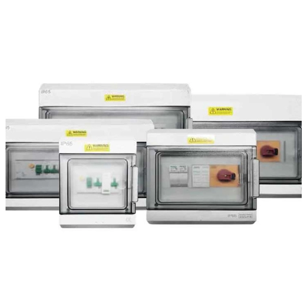
Tips for wiring in the main electrical distribution box
Practice good wiring: secure grounding, neat cable management, proper insulation, and correct wire gauge and breaker size. Include protection devices like breakers, fuses, and surge protectors—each circuit should have its own protection. Comply with standards: Follow NEC, IEC . In modern electrical systems, cable distribution boxes (also known as electrical distribution boxes or distribution boxes) play a crucial role as the key hub for managing, distributing, and protecting circuits. Whether in a home or an industrial facility, this box keeps your electrical setup organized, functional, and efficient. However, the key to. An electrical panel box, also known as a breaker box or a distribution board, is a crucial component of any electrical system. Connection method: Each switch takes a wire from the incoming point and connects it to the incoming end of the switch, or uses parallel connection to reduce the difficulty of wiring.
[PDF Version]
-
Relay protection function of the main switch
A protective relay is an automatic device that detects abnormalities in an electrical circuit and closes its contacts. This action completes the circuit breaker 's trip coil circuit, causing the breaker to trip and disconnect the faulty section from the healthy circuit. First, relays were used as signal repeaters within long-distance. Fingrid's application guideline for relay protection presents the operating principles of the relay protection in Fingrid's 110, 220 and 400 kV power networks and the requirements for operation of the protection systems of Fingrid customers (hereinafter referred to as 'customer'). The application. Provides protection, logic, and metering All-in-one solution. Three fundamental components required for each circuit breaker. While this is bad, It's not a.
-
Main Functions of Optical Wavelength Division Multiplexers
In fiber-optic communications, wavelength-division multiplexing (WDM) is a technology which multiplexes a number of optical carrier signals onto a single optical fiber by using different wavelengths (i. The concept involves sending multiple independent data streams down a single strand of fiber, much like transforming a single-lane road into a. 📦 For purchasing, use the RP Photonics Buyer's Guide for wavelength division multiplexing. It provides an expert-curated supplier directory, buyer-focused technical background information, and structured selection criteria to support professional procurement decisions. Tailored for professionals sourcing solutions from CommMesh, it. Optical multiplexing is the art of combining multiple optical signals into one to make full use of the immense bandwidth potential of an optical channel. It can perform additional roles like providing redundancy, supporting advanced topologies, reducing hardware and cost, etc.
[PDF Version]
-
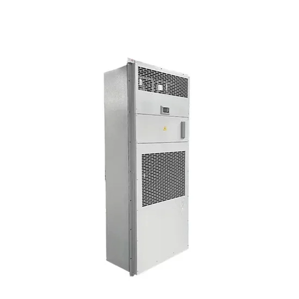
From the main distribution box to the sub-distribution boxes
Function: The MDB receives a high-voltage, high-amperage electrical supply and distributes it to several sub-distribution boards (SDBs) and other major electrical loads. It typically contains the main incoming breaker, busbars, and outgoing feeders. In any electrical system, the distribution box is the heart and brain, a critical component that safely manages and distributes power from the main source to various circuits. Several distribution boxes are designed for specific use in offices or industries. Electrical systems power our homes, offices, and industrial facilities, but behind every reliable electrical setup lies a crucial component that often goes unnoticed: the distribution box.
-
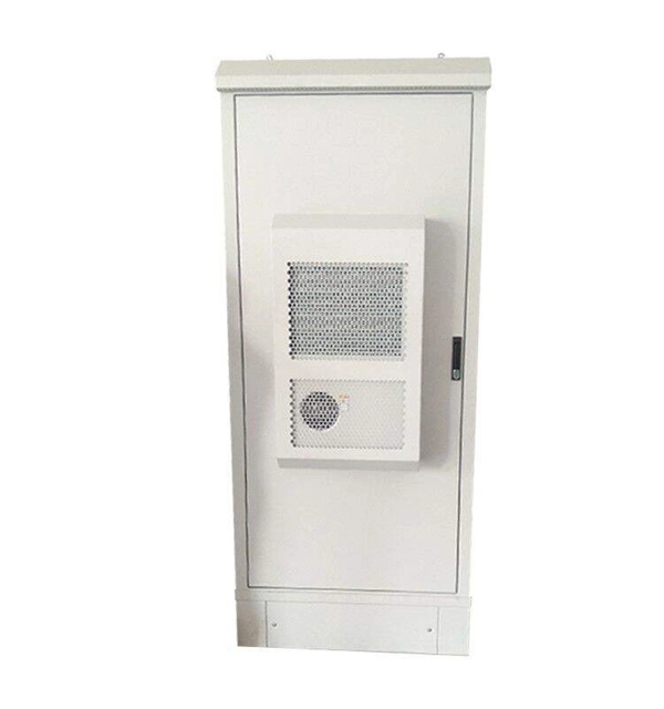
The main distribution box should use a four-pole switch
At incoming feeders or main distribution panels, always select 4P isolators or MCCBs (Molded Case Circuit Breakers). Standard IT systems usually do not provide a neutral line to the user, meaning a 4th pole is unnecessary. The correct choice depends on earthing system type and protection. In low-voltage three-phase four-wire distribution systems, disconnect switches, circuit breakers, or load switches are typically installed at the power source end of the distribution circuit. Their main functions are to disconnect or connect the circuit during normal operation, maintenance, or in. The choice between a 3-pole and 4-pole circuit breaker is often determined by the type of electrical system in use and the specific protection requirements. A 1P breaker handles one live wire. And if your system has significant neutral. When planning for systems, it is important to consider whether the UPS will be centralized or permanently connected and to use 3- and 4-pole devices appropriately for their locations and to ensure proper functionality of electrical systems. TP MCB: It is most commonly used type in all ordinary three phase supply.
[PDF Version]
-
Calculation of main cables for multi-layer distribution boxes
This Cable Sizing Calculator can calculate minimum active, neutral, and earth cable sizes in compliance with the international standard IEC 60364-5-52. Selecting the correct cable size is not just about electrical efficiency—it is a critical safety requirement. Under-sized cables lead to insulation failure, fire hazards, and significant equipment damage. This tool ensures your design coordinates protection, thermal limits, and voltage quality. Built on more than two decades of development, CableCalc helps electricians, contractors, engineers and consultants produce fast, accurate cable calculations, schedules and design documents with an intuitive modern interface. CableCalc BS7671 18-2 comes in four levels, catering to a wide range of. The different admissible methods of installation are listed in Figure G8, in conjonction with the different types of conductors and cables. 1 of IEC 60364-5-52) + : Permitted. Power Supply is 430V (P-P), 230 (P-N), 50Hz. 6 for Non Continuous Load & 1 for Continuous Load for Each Equipment. IEC, NEC, BS, etc) and some standards emphasise certain things over others.
[PDF Version]