-
Inspection after changing the setting value of the relay protection device
The purpose is to inspect the insulation between the relay terminals and the ground. Use a megohmmeter (such as 500V DC). Check wiring & . Protection Relay Testing is the procedure used to verify the performance, accuracy, timing, and operational condition of protective relays installed in electrical systems. These relays monitor electrical parameters such as current, voltage, frequency, impedance, and phase angle. But when it's needed, it has to perform. Servicing protective relays per manufacturer and NETA recommendations ensures they work properly to prevent injury or extensive damage to your plant during. Low Tension (LT) protection relays protect electrical systems by finding abnormal conditions such as Ground faults.
-
The numbers represent relay protection
Understanding ANSI standard relay numbers is crucial for anyone involved in electrical protection and control systems. These numbers, defined by the ANSI/IEEE C37. In electric power systems and industrial automation, ANSI Device Numbers can be used to identify equipment and devices in a system such as relays, circuit breakers, or instruments. The functions are supplemented by letters where amplification of the function is required. The other is given in IEC 60617 and uses.
-
How to label the wiring numbers in a distribution box
Step by step panel labeling per NEC: directories, circuits, wire colors, and safety. Get tips, examples, and printable templates to organize panels and reduce downtime. Proper electrical panel labeling is a critical safety requirement that helps prevent electrical accidents, ensures code compliance, and enables quick circuit identification during emergencies. You need to label every circuit breaker clearly and accurately to meet National Electrical Code (NEC). According to the U. Before you label. Knowing your distribution box helps you see which breaker does what. They help you turn off the right power fast in emergencies. Think of it as the distribution point where the main electrical wire comes into your home and then splits off into the various wires that service the various rooms.
-
Commercial Value of Hollow-Core Optical Fiber
The Global Hollow Core Optical Fiber (HCOF) Market is anticipated to witness robust growth at a CAGR of 17. 74 billion by 2030 from USD 1. 42 billion in 2024, fueled by ultra-fast connectivity, 5G deployment, optical networking, low-latency transmission, telecom innovation, and. Hollow by Material Type (Plastic, Glass), By End User (Aerospace and Defense, Telecommunication, Information Technology, Medical, Others), and By Region Forecast to 2034 The Hollow Core Optical Fibre Market size was estimated at USD 184. I need the full data tables, segment breakdown, and competitive landscape for detailed regional analysis and revenue estimates. Global Outlook – By Type Of Fiber (Photonic Bandgap Fibers, Anti-Resonant Fibers, Other Specialized Hollow-Core Fibers), By Material (Silica, Polymer, Other Materials), By Manufacturing Process (Extrusion Process, Draw Tower Process, Lasing And Sintering Methods, Other Advanced Manufacturing. The global hollow core optical fiber market size was valued at $190.
[PDF Version]
-
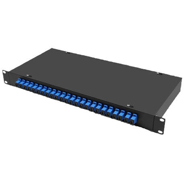
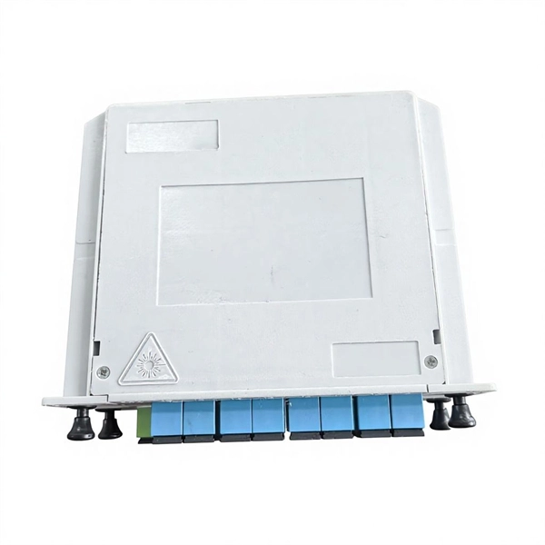
The attenuation value of the beam splitter of
In the context of beam splitters, attenuation can occur due to several factors, including absorption, reflection, and scattering. A beam splitter or beamsplitter is an optical device that splits a beam of light into a transmitted and a reflected beam. It is a crucial part of many optical experimental and measurement systems, such as interferometers, also finding widespread application in fibre optic telecommunications. In its. Signal attenuation refers to the reduction in the intensity of a light beam as it passes through a medium or a device. For a lossless beam splitter, R + T = 1. This theory has been developed for any type of BS and is based on the constancy of the reflection coefficients R (or the transmission coefficient T, where R + T.
-
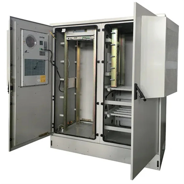
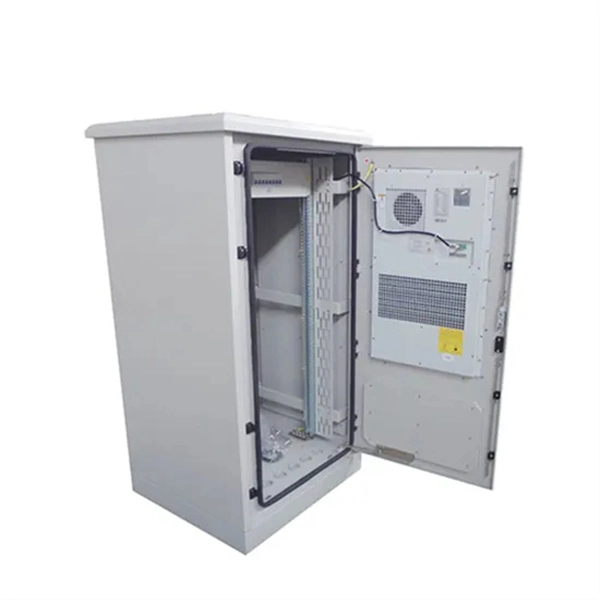
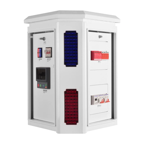
Value Assessment Report for Explosion-proof Distribution Boxes
This report is a detailed and comprehensive analysis for global Explosion-Proof Distribution Box market. The global market for Explosion-Proof Distribution Box was valued at US$ million in the year 2024 and is projected to reach a revised size of US$ million by 2031, growing at a CAGR of %during the forecast period. 5 billion by 2034, registering a CAGR of 7.
-
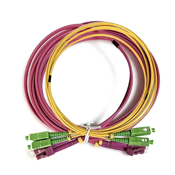
What is a normal optical attenuation value for fiber optic patch cords
For single-mode fiber (the type used in long-distance and high-speed networks), typical values under normal conditions are about 0. Under ideal conditions, those numbers drop to around 0. Attenuation in fiber optics is the gradual loss of light signal strength as it travels through a fiber cable. For speeds up to 200M, the light attenuation must be less than -25dBm. With light attenuation at -27dBm, speeds are limited to a maximum of 100M. This calculator helps you estimate the total attenuation (signal loss) in a fiber optic cable link. This can be due to a variety of factors: scattering and absorption, intrinsic loss, extrinsic loss, bending losses and more. If you don't know what kind of losses to expect in your system, you won't know how many other components.
-
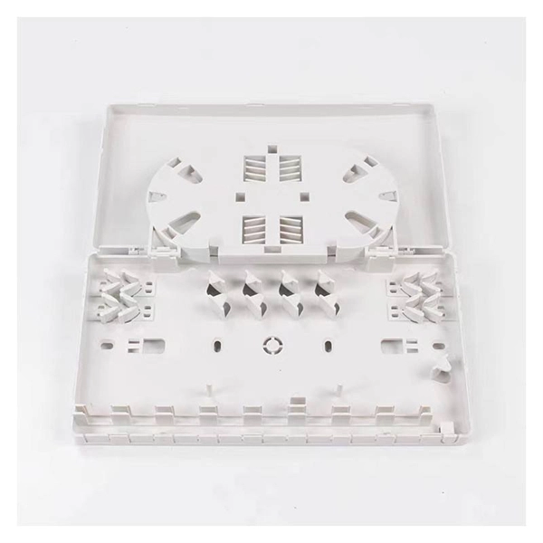
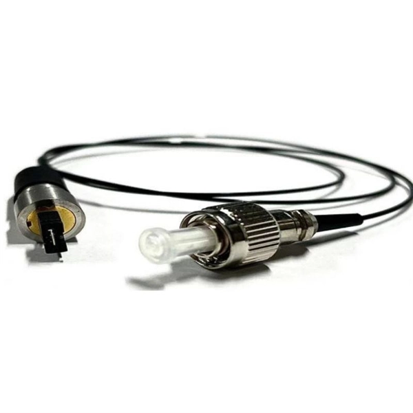
What is the maximum value of a fiber optic pigtail
The pigtail sets are designed to operate over a wide range of wavelengths, ranging from 850nm to 1300nm for multi-mode and 1310nm to 1550nm for single-mode fiber with guaranteed low loss and reliability. Each pigtail is individually tested and supplied with a test certificate. Executive Summary: A fiber optic pigtail is one of the most commonly specified yet least understood components in structured cabling. Get the wrong connector type, the wrong polish, or skip proper fusion splicing technique—and you're looking at elevated signal loss, increased back reflection, and a. OPTICO offers a full line of simplex or Bundle Fiber Pigtails. It is at the end of the SC/LC/ST/FC/E2000 / MTP/MPO/MTRJ optical fiber connector, the other end for termination by fusion or mechanical splicing fiber optic cable. 5m to 2m—that has a factory-terminated connector on one end and bare fiber on the other end. The connector end is polished and tested under factory conditions, ensuring low insertion loss and high. PPC ofers sets of high-performance pigtails colored in compliance with TIA-598-C standard for all types of fiber optic networks.
[PDF Version]
-
Understanding the wire numbers in the patch panel
Look at the back of the patch panel. Each port has a color-coded diagram showing exactly where each wire goes. In the United States, T568B is the standard for the vast majority of. The complete process for terminating cable runs at a patch panel, from mounting and cable management to punch-down, labeling, and testing every port. One commonly used wiring standard is T568B, which provides a standardized method for connecting Ethernet cables.