-
All-optical networking using optical switches
An all-optical Ethernet switch is a network switch whose service ports are entirely optical, meaning every interface uses fiber rather than copper. This design enables end-to-end optical signal transmission, avoiding the conversion between electrical and optical signals at the. Against this backdrop, all-optical Ethernet switches have emerged as a key solution that enables pure fiber-based networking with higher performance and future-ready scalability. Expressed in terms of analog bandwidth, a 1nm waveband translates to a bandwidth of 178GHz at 1300nm and. This paper first summarizes the topologies and traffic characteristics in data centers and analyzes the reasons and importance of moving to optical switching. They can function as core, aggregation, and access devices on campus networks and connect to upstream and downstream devices. ring numer-ous "optical to electrical to optical" (OEO) conversions. Transport is done with static point-to- oint optical links, while swi e connection-oriented data streams from input to output connections. Recent developments in all-optical circuit switching in combination.
[PDF Version]
-
Analysis of the advantages and disadvantages of using multimode fiber
Multimode fiber has a larger core (typically 50 or 62. 5 microns) and can carry multiple light signals, usually LEDS, at once. While that's great for short distances, those overlapping signals can bump into each other and cause distortion over longer distances. There are two main types of fiber optic cables: single mode and multimode. That makes picking between single mode and multimode fiber optic cables an. Single mode fiber has a very narrow core (around 8–10 microns in diameter), so it only allows one light signal (or "mode") to pass through at a time. It has a narrow core diameter of 8-10 microns and uses a laser or. Whether data is being moved between facilities, connected to a data centre, or integrated into a broader communications system, the type of optical fiber in use has a direct impact on speed, reliability, and long-term scalability.
[PDF Version]
-
When using wavelength division multiplexing technology
Wavelength Division Multiplexing (WDM) stands out as a cornerstone, enabling multiple data streams to travel simultaneously over a single fiber. This guide delves into the principles, types, applications, and future trends of WDM. Tailored for professionals sourcing solutions from CommMesh, it. Explore the fundamentals of Wavelength Division Multiplexing (WDM), its types, benefits, challenges, and future prospects in our detailed guide. With the endless upgrades and improvements, WDM technology is no longer just adopted by carriers and service providers, but also applied for. 📦 For purchasing, use the RP Photonics Buyer's Guide for wavelength division multiplexing. It provides an expert-curated supplier directory, buyer-focused technical background information, and structured selection criteria to support professional procurement decisions.
[PDF Version]
-
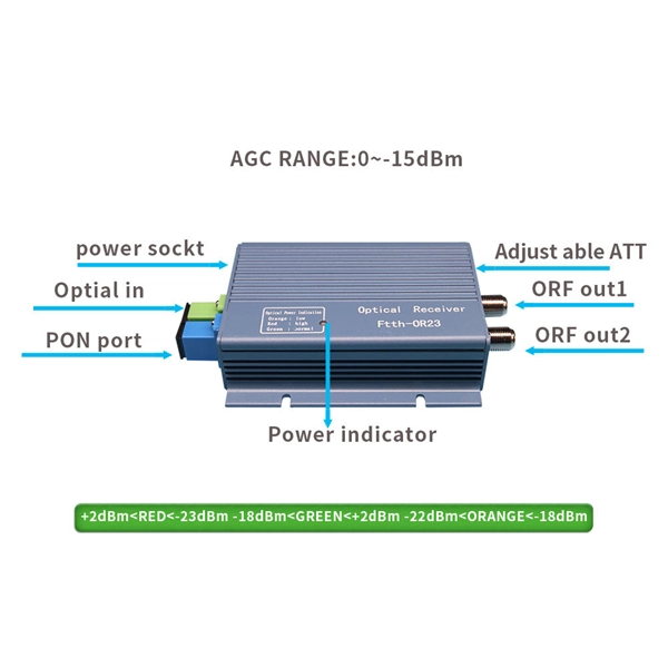
How to determine light attenuation of red light using an optical power meter
Optical attenuation compares input and output power on a logarithmic scale. When powers are in linear units, the loss in decibels is: Attenuation (dB) = 10 × log10 (Pin / Pout) If the link length L is provided, the attenuation coefficient is: Coefficient (dB/km) =. Analyze optical power drop across fibers and links. Switch units, lengths, and calculation modes easily. Needed when attenuation is an. Optical power, required for measuring source power, receiver power and, when used with a test source, loss or attenuation, is the most important parameter and is required for almost every fiber optic test. Backscatter and wavelength measurements are the next most important and bandwidth or. Optical power meters are a key element in the optimization and maintenance of such optical networks and of their components. But, for designers, just starting to work in the fiber-optic design space, measuring attenuation can seem like a monumental task.
[PDF Version]
-
What should be noted when using cable trays
Grounding and bonding are mandatory for metallic trays. Tray fill limits must be calculated properly. This article explains the main requirements and good practices for cable tray systems, including tray types, materials, loading, supports, bonding, cable selection, and installation details. The content is written to be SEO-friendly and compatible with Yoast SEO for WordPress. Introduction and. en completely installed, without damage either to conductors or structural system use maintain spacing or to keep cables in place when the tray is ect the minimum bend ra-dius for cables as they exit the bottom of the cable tray. A rung spacing of 6 to 9 inches (150 to 230 mm) is preferable when. What is the most common cause of cable failure? What is the most common cable management solution? What are the potential problems with cables? Any modern industrial, commercial, or data-intensive environment is mostly composed of effective cable management. A well-considered cable management. Related Articles: What Are The Common Types of Cable Trays 4. You should consider it as a series of instructions that make the buildings resistant to.
[PDF Version]
-

How to measure wear using fiber optic sensors
When the wafer dicing saw processes hard and brittle materials, the wear rate of the grinding wheel blade accelerates. To detect blade wear in time, a grinding wheel blade wear detection method based on a f.
-
Formula for bridge deck slope
By entering the deck length and slope ratio (like 1:48), it calculates the total slope drop, slope percentage, and angle, ensuring your deck avoids water pooling and lasts longer. and detailed Detailed drawings superstructures to engineers and technicia at a specific substructures. For decks. s of design and construction. While it is believed to be accurate, this information should not be used or relied upon for any specific application without competent professional examination and verification of its accuracy, suitability and applicability by a l censed engineer or architect. The. HEC-21 and HEC-22: These abbreviations refer to FHWA Hydraulic Engineering Circulars that are the basis for deck drain design [BDM 5. Design criteria: The primary reason for a good bridge deck drainage design is to provide for safe passage of vehicles during the design storm event.
[PDF Version]
-
How to set up a network using a fiber optic panel
If your ISP doesn't require a technician to set up your connection, these are the steps to self-install fiber internet: Locate your fiber network terminal. Connect the fiber terminal to the network box. Once you understand the basic concepts, you can check out my Recommended Equipment section toward the bottom of the. This guide walks you through the complete fiber installation process, from checking availability to optimizing your Wi-Fi network performance. Fiber transmits data using light signals through glass strands, delivering faster speeds and lower latency than cable or DSL connections that rely on. However, setting up a fiber optic connection to your router can seem daunting if you're unfamiliar with the process. Jump to: How to. In this article we'll break down how fiber internet is installed - from the network fiber drop outside your house to the in-home setup with your router and gateway - and what you should expect at each stage. Fiber optic internet is generally installed in the following 5 steps, which we'll dive.
[PDF Version]
-
Cost of laying optical cables using the airflow method
Prices vary based on the length of cable needed, installation method (aerial or underground), and labor rates in your area. Expect to pay $1 to $12 per linear foot, depending on project complexity and materials. By decoupling the empty microduct installation from the fiber blowing process, network operators can achieve up to 70% reduction in initial capital expenditure. Buying fiber optic installation services involves several cost components, with total price influenced by length, location, and access. Mainly manual. A fiber optic cable is made up of ultra-thin strands, each capable of carrying huge amounts of data at the speed of light. These strands are as fine as a human hair and are engineered for high-performance data transmission.
-
Positioning using a through-beam fiber optic sensor
Fiber optic position sensors utilize light transmitted through optical fibers to determine the position or displacement of an object. All information about the E20827 at a glance. We assist you with your requirements. ✓ Technical data ✓ Mounting and Installation Instructions ✓ CAD drawings ✓ Compatible Accessories There are several types of fiber optic sensors. Detection methods include thrubeam, reflective, retro-reflective, and definite-reflective. As the target. Through-beam sensors from Balluff serve to detect objects reliably, regardless of surface, color, material - even with a heavy gloss finish.
-
Companies using flame-retardant optical cables for smart buildings
This in-depth guide highlights the top 10 companies setting benchmarks in cable technology, regulatory compliance, and infrastructure resilience, as detailed in the Flame Retardant Cable Market by Type, Application, Insulation Material, Voltage, and More – Global. This in-depth guide highlights the top 10 companies setting benchmarks in cable technology, regulatory compliance, and infrastructure resilience, as detailed in the Flame Retardant Cable Market by Type, Application, Insulation Material, Voltage, and More – Global. The Global Fire Retardant Cable Market was valued at USD 11. 07 Billion in 2023 and is projected to reach USD 15. 6% during the forecast period (2024–2032). This growth is being driven by stringent fire safety regulations. Discover which global leaders are powering innovation and safety in the flame retardant cable market. Choosing the right Fire-Resistant Fiber. Our fire resistant/fire survival cables feature a steel wire/steel wire braiding/corrugated steel tape armour to provide mechanical strength. These indoor cabling fibers (drop cables) are those that connect ducts inside the buildings to individual rooms/floors.
[PDF Version]