-
Composition of butterfly-shaped drop fiber optic cable
FTTH Butterfly Optic Cables, also known as flat drop fiber cables, feature a compact flat profile with optical fibers placed at the center and reinforced by parallel strength members on both sides. Then, the cable is completed with LSZH sheath. Also, customers can specify your required connectors. Environmental Performance. Abalone Tech's 1/2/4F Self-supporting Butterfly Drop Cable is designed for aerial and duct installations in FTTH (Fiber-to-the-Home) and telecom networks. 5 kg/km Optical Performance: Insertion loss <0.
-
Maximum number of optical fiber cores in an optical cable
Multi-core fiber optic cables can contain 3 to 12 cores within a single cable. This significantly increases the data transmission rate, making them ideal for modern, high-demand applications. Multi-core fiber optic cables can serve multiple channels simultaneously to optimize. The number of optical cores in an optical fiber is the total number of equipment interfaces multiplied by 2, plus 10% to 20% of the spare quantity, and if the communication mode of the equipment has serial communication and equipment multiplexing, you can reduce the number of cores. Understanding Fiber Cores: Core: The central glass fiber that transmits light signals. Single-mode: A. The total number of cores for a 1pc fiber patch cable is calculated as the number of branches multiplied by the number of cores per branch (if there are no branches, the number of branches = 1). The following ZR Cable introduces some methods to determine the number of fiber cores.
[PDF Version]
-
What is the span of the North Asian trough-type cable tray
Electrical and telecommunication wires with short to intermediate support span 5 to 12 feet are usually installed on this type of trays. It has all the standard widths that ladder trays have and as it is non ventilated it is used for less heat genarating purposes. Their open rung structure allows air circulation and simplifies large power cable installation. Its Compact size makes it easier to position around and connect to equipment. Channel Cable Tray is available in. Trays shall be supported at a maximum span of 2. See sizing cable tray page A21.
-
Italian cable tray span
5–3 m) and verify the uniform load rating exceeds your cable weight plus a safety factor. Check deflection limits to protect terminations and fibre. Specify horizontal/vertical bends, tees, reducers, drop‑outs, and barriers. Choose radii that respect cable. As an industry leader in cable tray, Eaton offers one of the widest ranges of cable management solutions available in the market today with its B-Line series portfolio. It is designed for. Our cable tray design considerations guide details key factors to consider when designing cable tray systems for industrial and commercial applications. Eaton's submittal builder tool. maintain spacing or to keep cables in place when the tray is ect the minimum bend ra-dius for cables as they exit the bottom of the cable tray. A rung spacing of 6 to 9 inches (150 to 230 mm) is preferable when the cable tray cont d for instrumentation and control applications that require. Schiavetti Tekno, part of Spina Group, is a leading Italian manufacturer of cable trays and accessories for electrical and instrumentation systems. es in the industrial environment.
[PDF Version]
-
Canadian Large Span Cable Tray Specifications
The cable tray shall be classified by UL to NEC (2011 Edition), NEMA VE 1 and ANSI/NFPA 70 and be suitable for use as an equipment grounding connector. The width of the cable tray shall be (6" (150mm), 9" (225mm), 12" (300mm), 18" (450mm), 24" (600mm), 30" (750mm) or 36". Our knowledgeable production team works closely with each customer to provide quality solutions based on your schedule and budget. We want each and every experience with our company to be a good one. Through ongoing quality assurance analysis and evaluation of our manufacturing techniques, we. Product: BT Series, manufactured by Zip Cable Tray Systems (Division of RangeRack Inc. ) (1-866-818-0299, 514-428-1191, info@ziptray. ca), 100-C Hymus Boulevard, Pointe-Claire, Quebec, H9R 1E4, Canada. All illustrations, descriptions and technical information included in this document are provided as indications and can cable trays are equivalent. It is the consultant's requires USask Master Specification.
[PDF Version]
-
Unpacking of Drop Cable
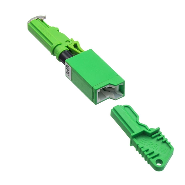
A drop cable is the final segment of the telecommunications network that physically connects a service provider's infrastructure to a customer's property. This cable runs from a point on the utility network (such as a pole, pedestal, or vault) directly to the side of a home or. A drop cable, commonly referred to as a cable drop, is a critical component in network connectivity, typically used to connect a computer's Network Interface Card (NIC) to a wall plate. WARNING: Unrestrained cable ends may cause injury to your eyes or body and can damage the cable fitting, or fibers if suddenly released from a coil. A cable drop, also known as a last-mile cable, connects the main distribution network to individual end-users, bridging the gap. Recognizing that no two networks are alike, Clearfield has developed the industry's widest choice of drop cable solutions – speeding deployments and providing the flexibility of configuration that best suits your network environment, network design and drop cable needs.
[PDF Version]
-
Maximum allowable voltage drop value of 10kV busbar
The formula used is IMAX = (I * 100) / (100 + VD), where I is the busbar current rating and VD is the allowable voltage drop. Typical values for LV installations are given below in Figure G27. 1) These voltage-drop limits refer to normal. Instant voltage drop limits calculator: NEC and IEC compliant, auto-applies 3%/5% rules for lighting, feeders. Enter nominal voltage and optional measured drop; get pass/fail, max allowable volts, length helper instantly. Design by percent limits: compute max length, minimum size or actual drop. Voltage drop is the reduction in voltage along a bus bar due to its resistance. This standard defines the design verification, test requirements, and thermal performance of the assemblies.
-
What is optical cable span
The span length is measured in kilometers and is a foundational specification in the design of any optical network. It represents the maximum distance the signal can traverse before its power or shape degrades past a usable threshold. A fiber optic span is a type of cable that is used to transmit light signals over long distances. Each of these strands act as an individual optical fiber that transmits light from one. what is the span of an optical fiber? I am new to the fiber-optic communication systems, and in reading some relevant papers, I faced to the term "span length" (such as long-span link) which I cannot distinguish it from the length of the cable. These active components can be a transmitting laser on one end and a receiver on the. Fiber optic cable transmission distance is determined by two primary physical factors that affect signal quality as light travels through the fiber medium.
[PDF Version]
-
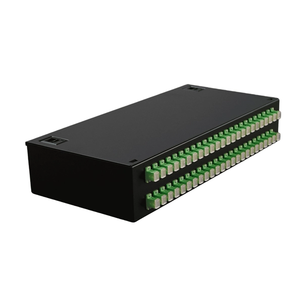
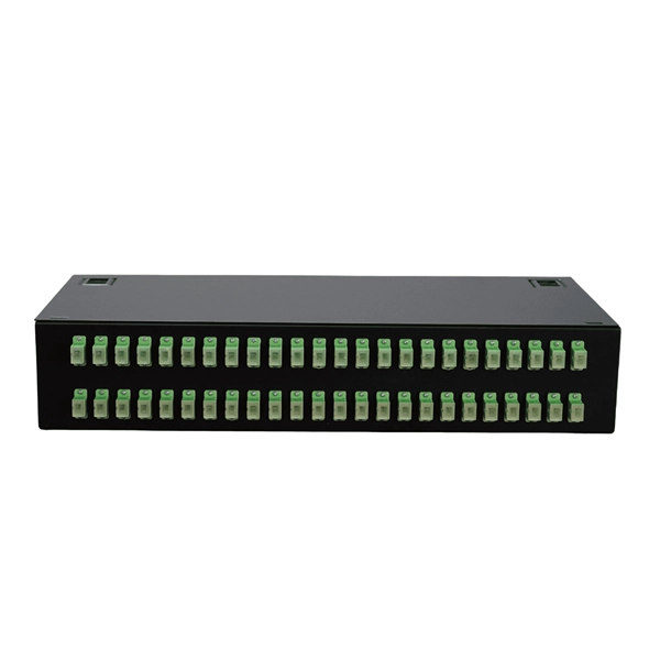
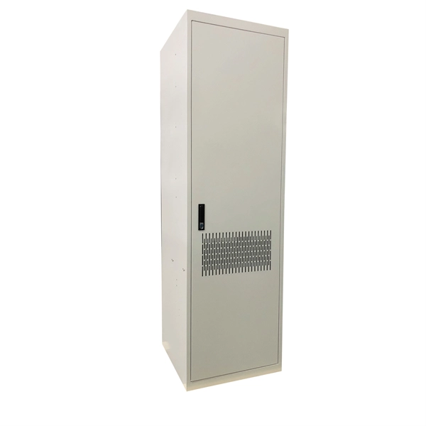
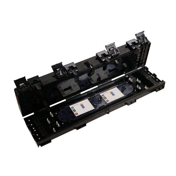
Telecom Fiber Optic Cable Drop Box
A Fiber Optic Termination Box is designed to secure and organize fiber optic connections, typically by linking fiber cables to an optical device through a patch cable. It can also function as a fiber optic distribu.
-
Optical cable channels are divided into
The light signal is divided into multiple channels with different frequencies and wavelengths, each transmitting a different data stream. In general, the fiber cable link system will be more secure if the fewer fiber cable segments. This region occupies a bandwidth of 95nm or 11THz! 8 cn cor where L is the fiber length, c is the speed of light, and ncor and nclad are the core and cladding refracitve indexes, respectively. Why not always use SMF? Optical phase information is lost in the detection process. What is a wavelength? What are optical wavelengths? What are nominal. In telecommunications, frequency-division multiplexing (FDM) is a technique by which the total bandwidth available in a communication medium is divided into a series of non-overlapping frequency bands, each of which is used to carry a separate signal. It essentially consists of a data transmitter, a transmission fiber (in some cases with built-in fiber amplifiers), and.
[PDF Version]