-
Multimode optical cable test length requirements
The cable should be longer than either of the following specifications, Event Dead Zone or Loss Dead Zone and the pulse length being used. Corning recommends that all fiber optic systems be tested to a minimum set of standards. So, you drop everything and i vestigate. He's right – it is n t working. Link testing of multimode segments should be done with an 850/1300nm dual wavelength unit. Since there is not an IEC/EIA. The length of launch cable used can very depending on the measurement needs. NEIS® are intended to be referenced in contrac documents for electrical construction ation or liability to users of this publication. Existence of a standard shall not preclude any member or nonmember of NECA or FOA from specifying or using. Other than for short-reach single-mode applications that are more susceptible to reflections and take connector reflectance into consideration, insertion loss testing, length, and polarity are really all you need for Tier 1 certification testing. Measured in decibels (dB), insertion loss is the. ANSI/TIA‑568.
[PDF Version]
-
How to test the continuity of a multimode fiber optic cable
The three standard methods for testing fiber optic cabling are a visible light source, power meter and light source, and optical time domain reflectometer (OTDR). Fiber optic testing for continuity is crucial in ensuring that light transmits through fiber optic cables without interruptions, safeguarding seamless data transmission. As the components like fiber, connectors, splices, LED or laser sources, detectors and receivers are being developed, testing confirms their performance specifications and helps. Fiber optic testing ensures the performance and reliability of fiber optic networks. It helps minimize downtime, reduce maintenance costs, and support system upgrades or reconfigurations. If it's a long outside plant cable with intermediate splices, you will probably want to verify the individual splices with an OTDR also, since that's the only way to make.
[PDF Version]
-
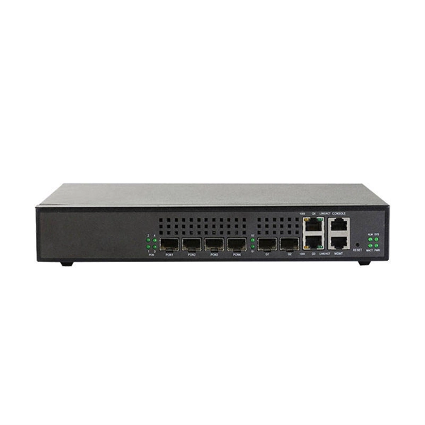
How to check optical loss on a Huijue switch
Execute the command, display transceiver [ interface interface-type interface-number | slot-id ] [ verbose ] to check the optical module information on the device interface. During use, reading optical module information helps understand its real-time operating status, enabling faster troubleshooting of link abnormalities. The following uses the. Here is an example on how to query or display optical power of an interface in a Huawei Router. from transceivers Check “Alarm information” section for warnings, LOS Alarm means no inbound signal, execute display this to check shutdown mode, execute undo shutdown if necessary. Execute the command, display.
-
How much splitter loss is used to calculate optical power
Insertion loss tells you how much weaker the signal becomes after passing through the splitter. Let's say you have a laser output at 0 dBm (which is 1 milliwatt of optical power). Factors influencing splitter loss include splitter. Instantly compute insertion loss, power at each subscriber port, and fade margin for PLC and FBT splitters — including dual cascade configurations. Covers GPON (1490 nm / 1310 nm), EPON, and RF video overlay (1550 nm). Add connector and splice quantities with realistic planning losses. Enable power budget to estimate received power and margin. Splitters are essential when you want one fiber line from a central office (like an ISP's headend or data center) to serve multiple homes or businesses.
-
What to do if fiber optic grating loss is high
When you face high loss in a fiber optic network, you need to act quickly to restore performance. You can address most issues by focusing on connector reconditioning and physical damage repair. (For the related question of what can disrupt a fiber link in the first place, see our companion piece on what can interfere with fiber optic. Signal loss in Fiber Optic networks can make data slow. High attenuation makes your system not work well. You should fix it fast to get speed and stability back. > You can solve this with simple steps. Each step helps you find problems and fix. Fiber loss, or attenuation, refers to the reduction in optical power as light travels through a fiber optic cable.
-
OTDR Measurement of Pigtail Splice Loss
The OTDR measures distance to the event and loss at an event - a connector or splice - between the two markers. To measure splice loss, move the two markers close to the splice to be measured, having each about the same distance from the center of the splice. If the pigtail is sufficiently long, 10 meters or so, VIAVI SolutionsTM Optical Time Domain Reflectometers (OTDRs) with pulses as short as 1 foot can perform these measurements. At sufficientl distances, such as 3 or. Download free OTDR Trainer Software for PCs After you study this page, you can download a free OTDR Trainer to run on your PC. The contractor submits test results.
-
High packet loss rate in fiber optic communication
A: For singlemode fiber, loss should be under 0. Q: Why is my fiber showing 10 dB loss?Bit Error Rate (BER) is a measure of signal integrity in data transmission systems, typically defined as the average ratio of the number of erroneously received bits to the total number of bits transmitted. It quantifies the frequency of channel errors, which are often caused by interference such. Significant signal loss (i., fiber optic loss) occurs within the fiber due to light absorption and scattering, affecting the reliability of optical transmission networks. When issues like signal loss, slow speeds, or intermittent connectivity arise, systematic troubleshooting is key.
-
How to choose the number of cores in a multimode fiber
Each network device typically requires at least two fiber cores: one for transmitting data and one for receiving data. For example, the total number of cores in an MTP®-8 trunk cable equals 4 (number of branches) x 8 (MTP-8. The number of optical cores in an optical fiber is the total number of equipment interfaces multiplied by 2, plus 10% to 20% of the spare quantity, and if the communication mode of the equipment has serial communication and equipment multiplexing, you can reduce the number of cores. When selecting fiber, the first step is to determine single mode or multimode, and. One key factor is the number of cores, which impacts how much data you can transmit. This post will guide you through understanding fiber optic cores and selecting the perfect cable for your needs. Single-mode: A. Fiber optic cables consist of multiple thin strands of glass or plastic, known as “cores. In the context of accelerating digitalization, the rational.
[PDF Version]
-
Tunisian Bending-Insensitive Fiber Multimode
This fiber is a bend-insensitive, graded-index multimode fiber designed for transmission speeds of 1 Gbps but also appropriate for transmission speeds of up to 10 Gb/s. But before adopting a new technology, rigorous testing must be. ClearCurve multimode laser-optimized, bend resilient fibers are widely deployed to deliver high data rate, low latency transmission. However, the performance and use of optical fiber will be se iously affected by the small bending radius.
-
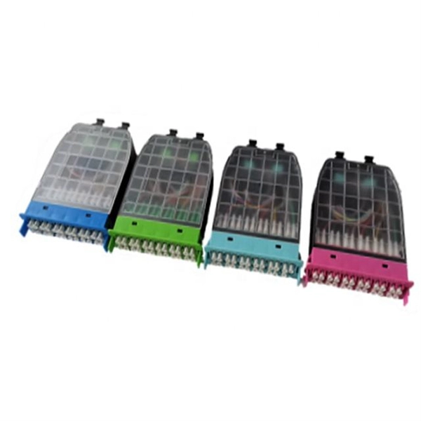
Splitter Optical Path Loss
5 dB depending on splitter type. Optional: patch panels, attenuators, or extra components. Helps cover dirt, aging, and measurement tolerances. Calculate insertion loss for passive optical splitters in PON and distribution networks. Excess loss accounts for manufacturing imperfections, typically 0. DISCLAIMER: These calculators are provided for. Optical splitters play a crucial role in Fiber to the Home (FTTH) Passive Optical Network (PON) systems, efficiently distributing a single optical signal to multiple destinations. Common values: 2, 4, 8, 16, 32, 64. Understanding the types of splitters, their impact on network performance, and how to measure their losses ensures high-quality network operation and facilitates optimal splitter selection based on. Understanding optical splitter loss isn't just about plugging numbers into a calculator.
[PDF Version]
-
How much loss does a 16-beam splitter have
5 dB loss, TIA allows 0. Splitter loss values are "Typical" and include a connector in and out. 5 dB, which could indicate dirty connectors, bad splices, or. Passive split links usually lose the most dB at the splitter, so we keep the optical budget and the installed route separate. Drop length Adds the final branch run to the split tree. Connector loss is always measured as a mated pair. It assures that the total output is never as high as the input. Insertion loss is the ratio of the optical power launched at the given input port of. The theoretical loss assumes perfect splitting with no imperfections. Optical splitters, including FBT (Fused Biconical Taper) couplers and PLC (Planar Lightwave Circuit) splitters, are common passive optical devices that split the fiber optic light into several parts by a certain ratio.
[PDF Version]
-
How to assess the loss of optical cables
In optical fiber cabling, it is necessary to calculate the maximum loss on a certain length of the line. Calculation formula of optical fiber loss: The Total Link Loss = Cable Attenuation + Connector Loss + Splice Loss Cable Attenuation (dB) = Maximum Cable Attenuation. Loss in optical fiber, also known as fiber optic attenuation or attenuation loss, measures the amount of light loss from input to output. This loss can be caused by a multitude of factors, ranging from intrinsic material properties to environmental conditions. While some loss is expected, excessive or unexpected loss can lead to poor performance, network downtime, and signal failure. For more accurate measurements, use mode conditioning on the fiber near the source. There are many reasons for optical fiber loss, such as optical fiber material's absorption/scattering of light energy, bending. Fiber optic loss is one of the most fundamental parameters in optical network engineering, yet it is often misunderstood as a purely theoretical value used only during design calculations.
[PDF Version]