-
Intelligent Power Distribution Unit PDU Full Name
IPDU Intelligent Power Distribution Unit - An Intelligent Power Distribution Unit (iPDU), also known as a Smart PDU or Intelligent PDU, is a critical component in modern data center infrastructure. iPDUs serve as a centralized power management solution that enhances the efficiency, reliability, and monitoring capabilities of power. The power distribution unit (PDU) market is projected to grow exponentially alongside the expansion of the global data center market from 2026 through 2030. Driven by the growth of hyperscale cloud, edge computing, and AI workloads, rack-level power distribution has become a strategic priority. Intelligent PDUs, or iPDUs, enable smarter IT infrastructure for increased uptime, increased efficiency, improved capacity.
-
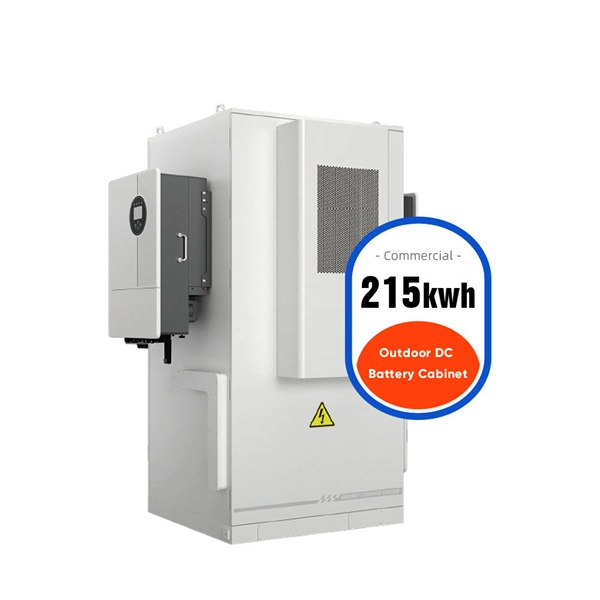
Intelligent Solution for Power Storage Cabinets in Mozambique
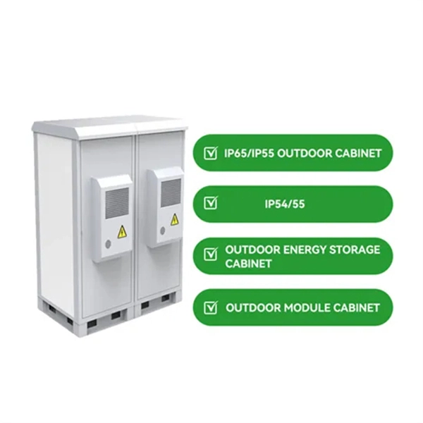
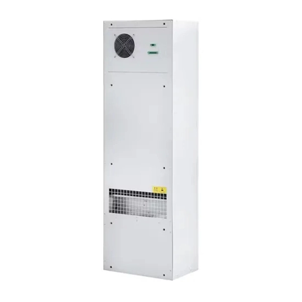
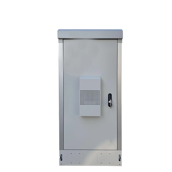
Meta Description: Discover the top large energy storage cabinet solutions for Mozambique's renewable energy sector. Learn how to choose reliable systems, compare lithium-ion vs. lead-acid options, and explore real-world applications in mining and agriculture. With 300+ days of annual sunshine. With 58% of Mozambicans lacking access to. e-STORAGE is a brand of Canadian Solar, Inc. The project was carried out in close collaboration with the German Corporation for International Cooperation (GIZ) and the. High-Capacity Energy Storage: With a capacity of 80-120kWh, this cabinet is ideal for small businesses and commercial applications, providing a reliable source of power during outages. Combines high-voltage lithium battery packs, BMS, fire protection, power distribution, and cooling into a single. As Mozambique accelerates its industrial development, reliable energy storage solutions have become critical for factories, mining operations, and infrastructure projects. Mozambique's Energy Storage Revolution: Powering Sustainable. These cabinets serve as centralized hubs for managing and storing.
[PDF Version]
-
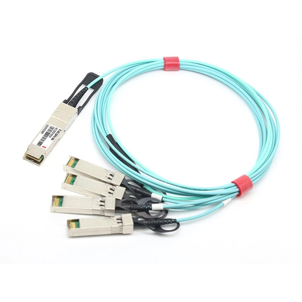
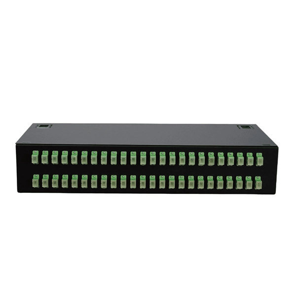
How to connect the power supply to a fiber optic switch
We'll show you how to connect power and network using a fiber optic cable linked to the core switch in the control room. No extra adapters needed—just plug directly into an AC outlet. This setup is perfect for extending your network to outdoor IP cameras or remote locations. more Learn. Fiber connectivity to the power supply will pass through a standards-based SFP (small form-factor pluggable) interface which allows operators to communicate with the power supply using their chosen vendor solution. The opportunities and efficiencies they offer speak for themselves—but, as they spread to locations both indoors and out, you're probably feeling the crunch caused by not having enough. While in this post, we mainly focus on the PoE system that using fiber optic with power to solve unusual applications specifically in real life, which may need to achieve greater distance, higher bandwidth, or better reliability. Concerns go from laying. CONFIGURING THE SWITCH IN DESIGO CC/CERBERUS DMS.
[PDF Version]
-
How to pull up a power fiber optic cable
Fiber optic cables should always be pulled by the strengthened yarn fibers inside the outer jacket. This article explores recommendations for pulling and installing fiber optic cable. Most fiber optic cables boast a pull strength of 100 – 200. Fiber optic cable is surprisingly strong, durable and pliable; however, several best practices should be followed to ensure a successful cable installation. Most fiber damage does not come from normal operation after the system is live. More than half of cable problems happen because of wrong pulling. In 2025, new tools like hydraulic blowers, smart monitors, and better grips help you lower risks, save money, and keep the. A duct is available from point A to point B, a pull tape is blown in, a fiber optic cable is attached to it and the cable is pulled through the duct.
-

How to route fiber optic cables for high-voltage power lines
This technique takes a small, lightweight fiber optic cable and wraps it around or lashes it to the power line. The cable is called optical power attached cable (OPAC), and it is lashed to the power cable with a specialized tool that is pulled from the ground, such as a. Installing ADSS (All-Dielectric Self-Supporting) cables near live power lines demands precision, compliance with safety standards, and an understanding of high-voltage risks. This guide from GL FIBER breaks down the process into actionable steps, aligned with IEEE 524 and IEC 61935-1 protocols, to. Most aerial fiber optic cables are installed by lashing to a steel messenger wire strung between poles, but there is a category of cables with special high-strength jacket designs called all-dielectric self-supporting (ADSS) cables. ADSS cables are designed to withstand very high-tension loads. bles in a high voltage environment, with typical line voltages of 115 kV or more, requires the evaluation of certain critical parameters. Curr ntly, there are a limited number of industry documents that address the requirements for optical fiber cables near high voltage circuits.
[PDF Version]
-
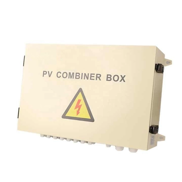
Anti-residual power systems for wind power generation
A hybrid wind-solar energy system consists of the following components: 1. Solar panels 2. Wind turbine – see our guide to the best wind turbines 3. Charge controller 4. Battery bank 5. Inverter 6. Power dis.
-
DC busbar power failure
If the busbar protection fails to trip when an external fault occurs or if it falsely trips while in use, the power system could become unstable. A total power outage will result from this. Regular dielectric testing is crucial to verify the quality of insulation and ensure that busbars can perform reliably under both normal. Busbar insulators are the backbone of electrical systems, ensuring safe power distribution by isolating conductors and preventing faults. However, harsh operating conditions, material degradation, and improper maintenance can lead to insulator failures—jeopardizing safety and system reliability. The DC-link capacitor selection is one of the first and most important steps. Consequently, power busing design needs critical consideration in terms of performance under converter operation, asymmetric loading, short-circuits, thermal and insulation breakdown.
[PDF Version]
-
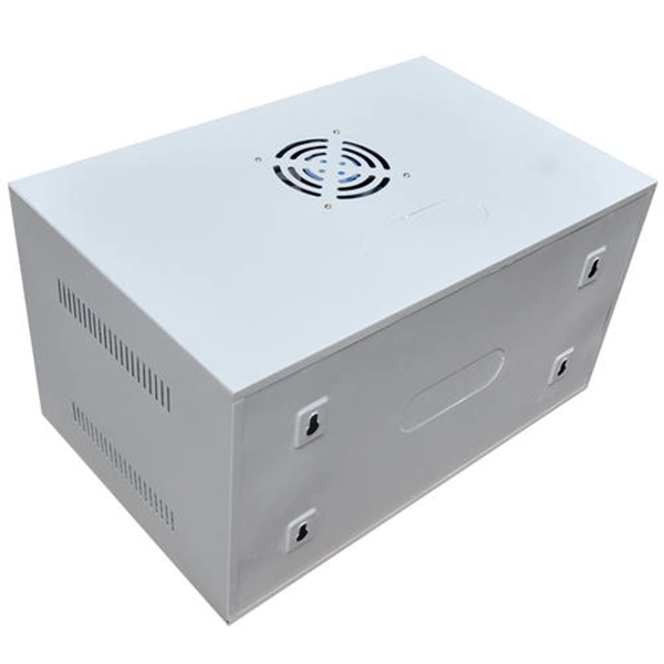
Dedicated power distribution box for engine room
Paneltronics' enclosure box-build assemblies provide efficient consolidated assembly solutions for several common functions and requirements including: 1. Ignition protection 2. Common buses 3. Control.
-
Increase the light output power of the optical module
An optical amplifier is a device which receives some input signal light and generates an output signal with higher optical power. Typically, inputs and outputs are laser beams (very rarely other types of light beams), either propagating as Gaussian beams in free space or in a fiber. At the receiver end, the optical signals are reconverted into electrical. In this guide, we will explain what optical signal strength is, how to check it on Cisco IOS using the command line, and how to troubleshoot common light level issues. Assume the. This application note gives a short introduction to optical modules and the need of an optimized power tree in them and then concentrates on the use cases and benefits of four-switch and inverting buck-boost converters inside optical modules.
-
Power Grid Optical Cable Operation Level
Key OPGW testing methods include visual inspection, OTDR testing, optical power meter testing, continuity tests, and various mechanical and environmental tests. Each method targets a specific aspect of cable performance and safety. OPGW stands for Optical Ground Wire. These cables are used on high voltage power lines. I have managed many projects where I personally oversaw the testing process. I know that if testing. This specification defines the design, material, performance and test requirements for fibre optic cable to support the fibre optic telecommunication needs. How to calculate the required fault. ion infrastructure. Optical Ground Wire (OPGW)/Underground Fiber Optic Cable (UGFO) plays a crucial role in ensuring seamless data exchange, real-time monitoring, and reliable operati n of power systems. However, with increasing demands and multiple stakeholders involved in fiber usage, it became.
[PDF Version]
-
Incident Power in Fiber Optic Communication
The incident optical power is used to suppress nonlinear effects and ensure transmission quality. In the following figure, optical power at point C is the incident optical power. Why Do We Need Incident Optical Power? The transmission performance of a WDM system is affected by the. This AE Note explains the differences between Optical Return Loss (ORL) and Back Reflectance in fiber optic systems. Even minor deviations—whether too high, too low, or unstable—can impact signal integrity, trigger service alarms, or interrupt traffic on DWDM, OTN, or long-haul optical line systems.