-
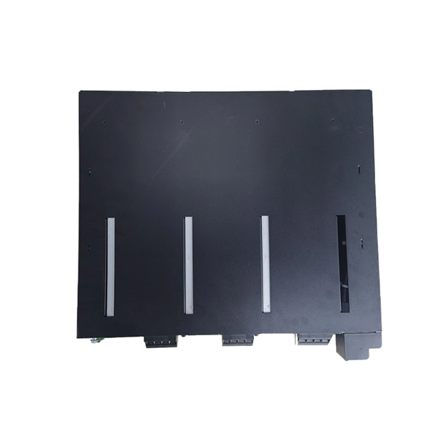
Photovoltaic combiner box ISO standard
IEC 62548: This standard specifically addresses design requirements for PV arrays, including detailed specifications for combiner boxes. ance cables by combining strings at the array locat ciency, reliability and safety in solar energy systems. They enable centralized management in large-scale and remote installation ity), equipment aging, and poor installation practices. Additionally, it facilitates efficient execution of regular. A solar combiner box is a crucial component in solar energy systems, designed to consolidate the outputs of multiple solar panel strings into a single output that connects to an inverter. Eaton (Bussmann) understands that no two PV installations are alike and that the. Often misunderstood by novices as a simple "junction box," a commercial-grade combiner box is, in reality, the most critical safety barrier and diagnostic hub located between the photovoltaic array and the inverter.
[PDF Version]
-
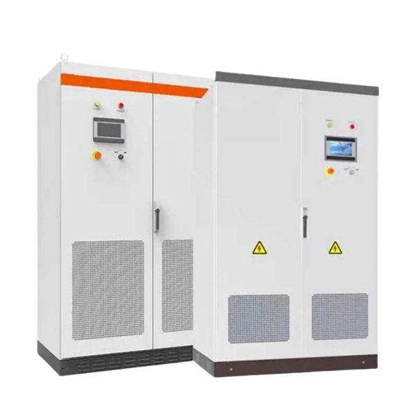
Boost Module Photovoltaic Panel
This example uses a boost DC-DC converter to control the solar PV power. The boost converter operates in both MPPT mode and voltage control mode. The model uses the voltage control mode only when t.
-
Photovoltaic Power Generation Module Installation Method
This article walks you through the basics of PV system installation, focusing on the practical steps from mounting modules to connecting the inverter to the electrical grid, and emphasizes the importance of ongoing maintenance to optimize system performance. (hereinafter referred to as LONGi). Please abide by all safety precautions in this guide and local regulations. •Installation of. Installing photovoltaic (PV) systems is a key stride toward embracing renewable energy, which is crucial for reducing carbon footprints and fostering sustainable energy use. Starting with a detailed site assessment to evaluate solar potential and optimal setup, the process ensures efficiency and. Protective earth grounding of the individual photovoltaic modules is achieved by securing the modules to the SRS mounting system. This guide provides detailed instructions for the proper application of SIRIUS PV modules.
[PDF Version]
-
How to use a 1500V photovoltaic multimeter
Connect the positive lead of the multimeter to the positive terminal or wire of the solar panel. In the rapidly evolving solar industry, the shift from 1000V to 1500V DC systems has become the new standard for utility-scale projects. While this increases efficiency, it creates a dangerous gap in the toolkits of many technicians. Whether you're working with a utility-scale solar photovoltaic (PV) array, wind power, an electric railway, or a data center, the Fluke 283 FC has been. 🔋 Maximize the safety and performance of your solar PV system with the PV-ISOTEST 1500VDC insulation meter! Designed to meet IEC/EN62446 standards, this professional-grade tool allows for accurate insulation resistance testing, ground fault localization, and PV system verification.
-
10kV Busbar Voltage Testing Standard
IEC 61439 is a standard developed by the International Electrotechnical Commission (IEC) that covers design verification for low-voltage electrical products and assemblies. The IEC 61439. 7 cycles of 24 h each to salt mist test according to IEC 60068-2-11; (Test Ka: Salt mist), at a temperature of (35 ± 2) °C. The test shall be carried out according to IEC 60068-2-2 Test Bb, at a temperature of 70 °C, with natural air circulation, for a duration of 168 h (7 days) and with a recovery. ULTRUS™ helps companies work smarter and win more with powerful software to manage regulatory, supply chain and sustainability challenges. Consistent performance benchmarking testing capabilities for professional PC users. Award-winning software and advisory services for ESG management and. The purpose of this method is to verify the functionalities of a Metal Enclosed Busb ar. How do you check and maintain busbars? What are the faults of busbar? What is bus bar in DB? For complete safety instructions and precautions, always refer to the test equipment instruction manual.
[PDF Version]
-
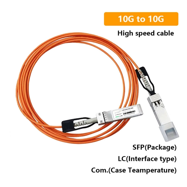
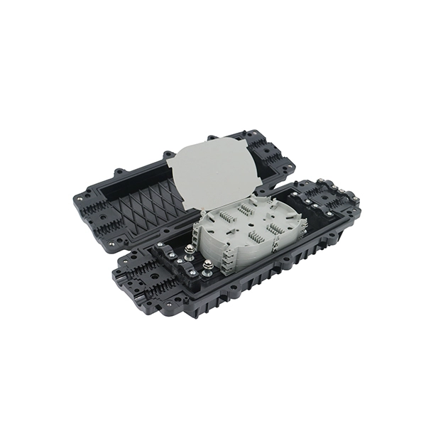
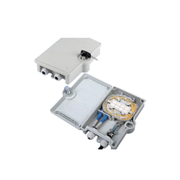
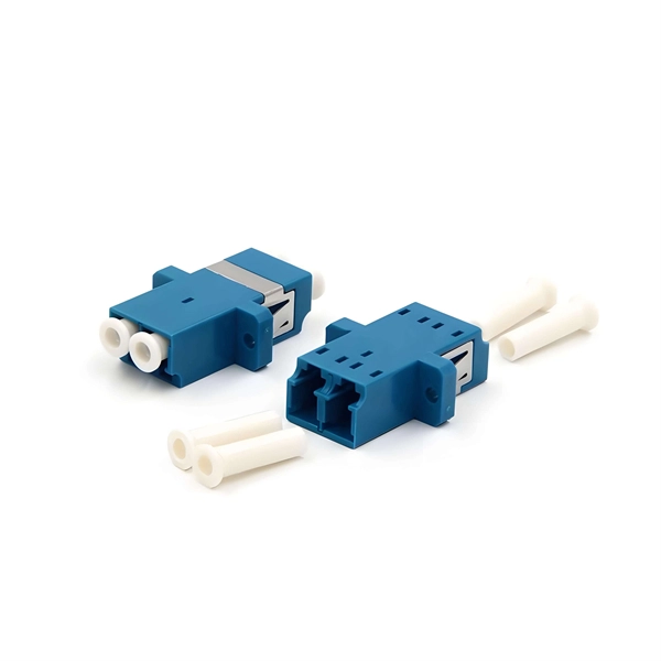
Standard for the length of optical cables connected to junction boxes
Type AC cable must be secured within 12 in. of every outlet box, junction box, cabinet, or fitting and at intervals not exceeding 4½ ft [320. 22, which applies when. Part II of Article 770 provides the requirements for cables outside and entering buildings. Of course, if it's entering a building it would necessarily be outside unless it is entering from within another building that shares a common wall. So basically, this is about outdoor cables. It defines a minimum leve e fiber optic cabling extends between buildings. Although the standard covers premises installations, many of the provisions included here ar SI/ NFPA 70, the National Electrical Code (NEC). (FOA) was founded in 1995 to help develop the workforce to build the fiber optic networks to support a rapid expansion in communications and the Internet.
-
National Standard for 90-degree Cable Tray Elbows
The National Electrical Manufacturers Association (NEMA) Standard VE 1-2002 provides guidance for metal cable trays and associated fittings designed for use in accordance with the rules of the NEC. They define a minimum baseline of quality and workmanshi for installing electrical products and systems. The. This standard is issued jointly by Canadian Standards Association (operating as “CSA Group”) and the National Electrical Manufacturers Association (NEMA). Comments or proposals for revisions on any part of the standard may be submitted to CSA Group or NEMA at any time. These systems have 1-1/8″ wide side rail flanges and 4-hole splice plates. Class 2 Tray Fittings are designed for use with NEMA Class 20A, 20B, and 20C Cable Trays.