-
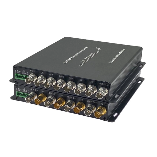
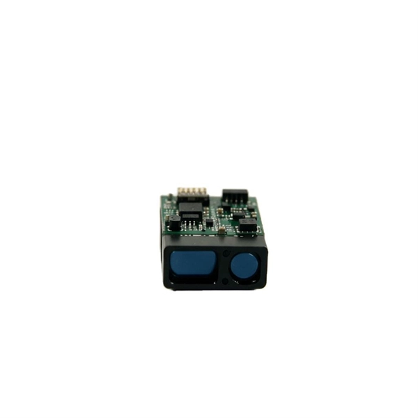
Normal power values for optical modules
Generally, for a standard 10G-SR (Short Range) module, the RX power should be between -2 dBm and -9 dBm. Always ensure the level is higher than the “Receiver Sensitivity” limit found in the Cisco datasheet. The TX (transmit) and RX (receive) power levels significantly affect everything from signal strength to transmission distances and the overall optical power. This guide provides average transmit and receive power ranges for transceiver modules. Transceivers are manufactured to meet the specifications (usually of the IEEE standards) and ranges represent the values that the part can operate within. The fact that one part can be at the lower end of the. For network engineers working with fiber optics (SFP, SFP+, QSFP), understanding TX (Transmit) and RX (Receive) signal strength is critical. However, in practical use, we adopt the average Tx power.
[PDF Version]
-
Price of pigtail box manufacturing process
IMARC Group's report titled “Corrugated Box Manufacturing Plant Project Report 2024: Industry Trends, Plant Setup, Machinery, Raw Materials, Investment Opportunities, Cost and Revenue”provides a co.
-
Cable tray dip coating process
Steel trays get dipped in very hot molten zinc (around 450°C). The zinc bonds tightly to the steel, creating a thick, tough layer. Process: Degreasing → Pickling → Rinsing → Fluxing → Drying → Hot-dip galvanizing → Cooling → Passivation (optional) → Inspection. Hot-dip galvanizing is a process that enhances the durability of cable trays by creating a protective zinc coating, safeguarding them from corrosion. It is cost-effective, protects against a wide variety of environmental chemicals, and is self-healing if an area becomes unprotected through cuts or scratches. Steel is coated with zinc through electrolysis by dipping steel into a bath of. Legrand's offer of global solutions for wiremesh cable trays (and accessories) is one of the most complete on the market. It offers true freedom by allowing multiple configurations in a wide choice of finishes for optimal integration into any environment.
[PDF Version]
-
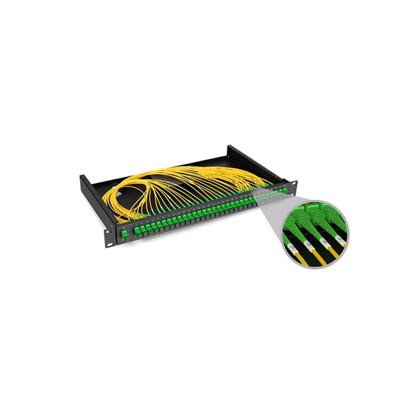
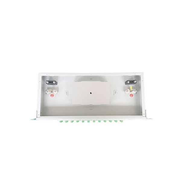
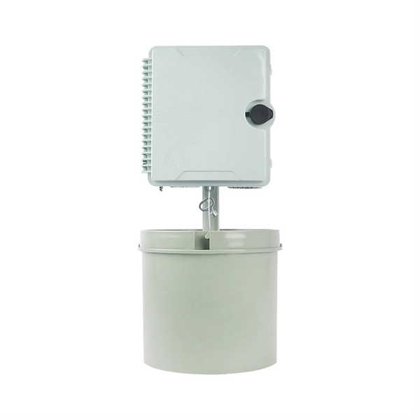
Customization Process for Low-Noise Fiber Optic Distribution Frames for Broadcast Transmission
This complete guide explores everything you need to know about ODFs — from their structure, types, and key components, to installation best practices and modern design trends. It includes first determining the type of communication system (s) which will be carried over the network, the geographic layout (premises, campus, outside. An Optical Distribution Frame (ODF) is the central hub for fiber splicing, termination, patching, and cable protection in modern optical networks. Why do operators, designers, and installers use additional fiber optic hardware racks for cable and fiber management? The active electronics are the most expensive part of the.
-
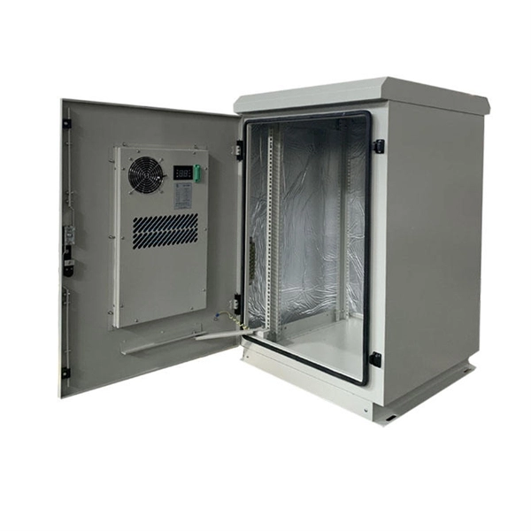
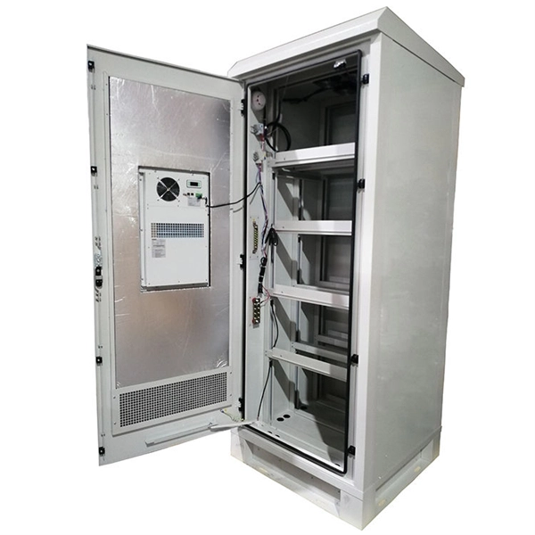
Process of making a small electrical distribution box
Construction begins by preparing the enclosure, drilling holes for the power inlet, output receptacles, and required ventilation. After smoothing the holes, mount the circuit breaker panel or rail securely inside the box, followed by the attachment of the ground and neutral bus. A distribution box is an essential component in electrical engineering, widely applied in residential, commercial, and industrial projects. It is very unique design and made by very small tools. This post is a case study of a personal project I completed based on South Korean standards (single-phase 220V / 60Hz) and is NOT a universal tutorial. Do not attempt this unless. Once I thought up the idea of the remote starter and switch stuff, i needed a way for them to not interfere with each other. Solution: diodes, the electronic one way valve.
-

Fiber Optic Cable Splicing Process and Stitching Steps
Learn how to splice fiber optic cable using fusion splicing with this complete step-by-step guide. Includes tools, best practices, loss standards (ITU-T G. 652), cost analysis, and FAQs for network engineers and installers. Ensure Your Splicing Tools are Clean – #2. Before jumping into the physical steps, it's important to understand the two primary methods of fiber splicing: fusion splicing and. Splicing fiber optic cable is an extremely important phase for making dependable, high-speed communication infrastructures. more Learn how to splice fiber optic cable step by step in this complete guide! In this. Don't Miss this Super-Detailed Tutorial on Fiber Splicing and Winding! Don't Miss this Super-Detailed Tutorial on Fiber Splicing and Winding! The operation and skills of fiber optic fusion splicing technology can be mainly divided into five steps: fiber stripping, fiber cutting, fiber melting. Fiber optic cable splicing connects two cables, creating a strong link for fast data transmission. Splicing fiber helps light signals move easily, ensuring your internet connection remains reliable.
[PDF Version]
-
10kV bus voltage exceeds the upper limit
The DC bus has exceeded the maximum value. Reduce the mechanical load and/or rate of deceleration. The DC bus overvoltage fault, also called a DC bus error or simply an overvoltage fault, is among the most common faults on an AC variable frequency drive. Because it's so common, some newer drives try to assist with locating the issue by providing more information about what the drive was doing. The DC bus voltage is too high. Thanks Engr Raja Haroon Rasheed Posted: 2020-07-03 01:39 PM. Last Modified:. Regenerative drives are built to handle excess energy, but when voltage levels spike beyond safe limits, your drive trips to protect itself. Maybe it only happens during high deceleration? Or maybe it's completely random? Either way, production stops, and downtime starts adding up fast. PV input voltage in Datasheet is not exceeded. If the measured voltage value is close to the maximum MPPT range threshold, it is recommended to reduce the number of photovoltaic panels in the corresponding sting.
[PDF Version]
-
35KV bus voltage too high
A DC bus overvoltage fault typically comes from one of three causes: high incoming line voltage, a motor being back-driven by a heavy load, or electrical harmonics on the supply power. Mechanical issues are the most common trigger. My SRT 5kxli had a issue in which dc bus over voltage is occurred in logs and load dropped. Thanks Engr Raja Haroon Rasheed Posted: 2020-07-03 01:39 PM. Last Modified:. 35 kV switchgear supports sub-transmission and industrial feeders that need higher insulation and fault duty. Voltage/BIL: 35 kV class, typical BIL 170 kV. Short-circuit: 25–40 kA short-time withstand common; confirm with system fault. Bus voltage is the electrical potential measured on a shared conductor, or “bus,” that distributes power or signals between components in a system. Epoxy insulation is available at 600 V as an option. If it overshoots or brakes, the DC link will increase until you reach the tripping voltage somewhere close to 1200 V for a 600 V drive.
[PDF Version]
-
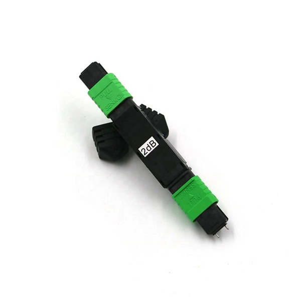
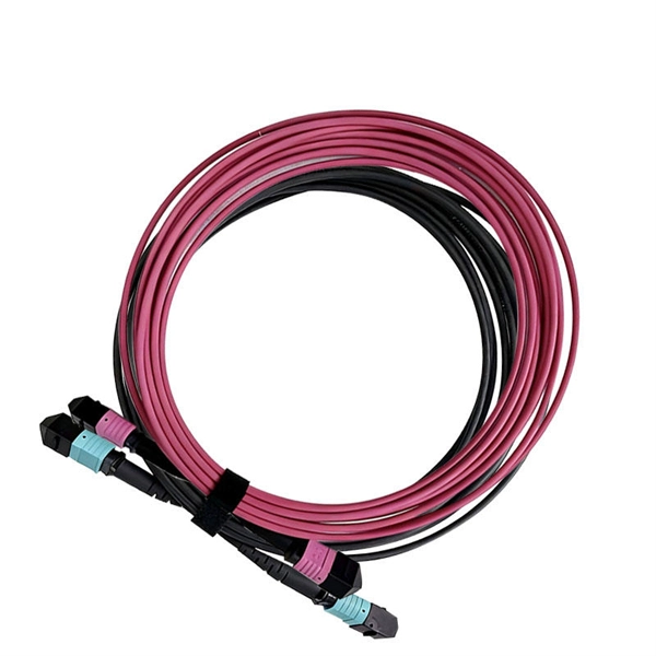
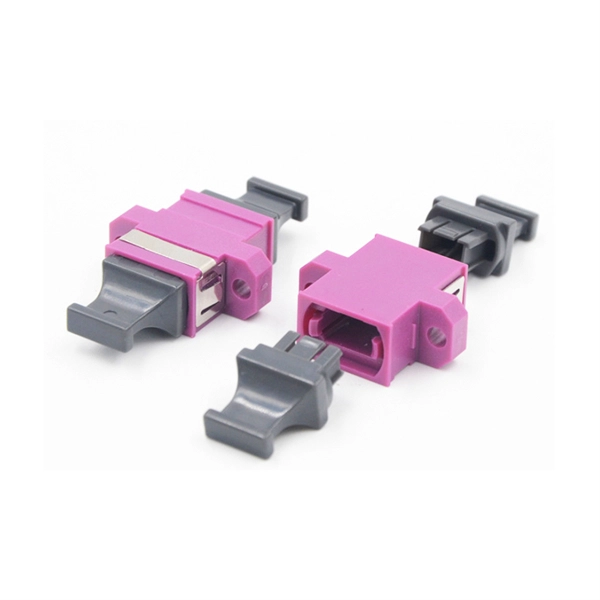
Intelligent Customization Process for MTP Adapter Modules for Railway Communication
Klaus Lechtenbörger from EPLAN shows how P&ID flow diagrams can be created efficiently in the MTP tool chain and exported as MTP. Laurids Beckhoff guides you through the process of module definition and development along with automatic PLC and human-machine interface. The Module Type Package (MTP) is a concept that allows process technology plants to leverage maximum potential across the board, from the planning phase through to operation. This makes MTP a crucial component in the development of future modular automation solutions. 0 as new consistent set of documents! Member Review for MTP Specification part 1 has been kicked off on June 12, 2024 After the initial release, a release of the MTP Specification is planned every 2 years. What is MTP? In many places, the process industry is characterized by large systems that have been in operation continuously. MTP is a description semantic – comparable to a device driver – with the help of which your system, laboratory or technical center can be reconfigured quickly and easily. Plug & Produce enables modules and devices to be integrated as easily as a printer with a PC.
[PDF Version]
-
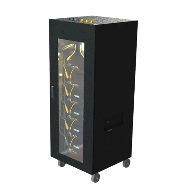
Customization Process for Energy-Saving PLC Splitters in Broadcast Transmission
The non-uniform planar lightwave circuit (PLC) splitter with one primary and multiple signal distribution function is one of the most crucial devices in Fiber-To-The-Room (FTTR) technology. Reducing the dev.
-
Fabrication process of optical fiber and cable
The manufacturing sequence can be broken into two broad phases: fiber drawing (producing the raw optical fiber) and cable construction (assembling fibers into a rugged, deployable product). Both phases demand tightly controlled materials, temperatures, and mechanical tolerances. Which are the six main parts of optical fiber? The manufacturing process consists of major steps, including glass deposition, preform fabrication, and fiber drawing, shown schematically below: Each step applies specialized techniques to realize the stringent requirements of optical signal. The manufacturing process of fiber optic cables is a fascinating journey involving cutting-edge technology, precision engineering, and strict quality control. This hair-thin strand of glass or plastic transmits data as pulses of light over long distances with minimal signal loss. This process begins with the creation of a preform, which serves as the foundation for the optical fibers within the cable. The preform. Optical cables are born from ultra-pure glass preforms, drawn into hair-thin fibers, coated for protection, bundled strategically, and encased in durable jackets.
[PDF Version]
-
What is the process of installing mobile optical cables
Installing an optical cable involves selecting the right fiber type, carefully routing it without damaging the glass inside, terminating the ends with connectors, and testing the finished link for signal loss. In this article we'll break down how fiber internet is installed - from the network fiber drop outside your house to the in-home setup with your router and gateway - and what you should expect at each stage. The process requires more precision than copper cabling, but with the right tools and. The Professional Association Of Fiber Optics www. org The Fiber Optic Association, Inc. (FOA) was founded in 1995 to help develop the workforce to build the fiber optic networks to support a rapid expansion in communications and the Internet. The charter of the FOA was to promote professionalism. If you're considering getting AT&T Fiber service or upgrading your current internet plan to fiber optic internet, learn more about the fiber internet installation process. It's called this because it uses light-based (optical) technology. Imagine how information travels across.
[PDF Version]