-

Distance between primary and secondary power distribution boxes
A minimum of 24 inches of cover for secondary (0 − 750 V) electric service, or 30 inches minimum cover for primary (over 750 V) is required for electric trench only. Cover is the distance from the outer surface of an underground facility to the top of the final grade. Primary distribution systems consist of feeders that deliver power from distribution substations to distribution transformers. At this. nt, and/or other requirements. ” Strict adherence to ons for manholes are critical. At a. This document is published to provide specifications, information, and guidance to assist developers in planning for and obtaining proper and prompt electric facilities to serve underground developments in the FirstEnergy Service territory. The requirements detailed in this document address conduit.
-
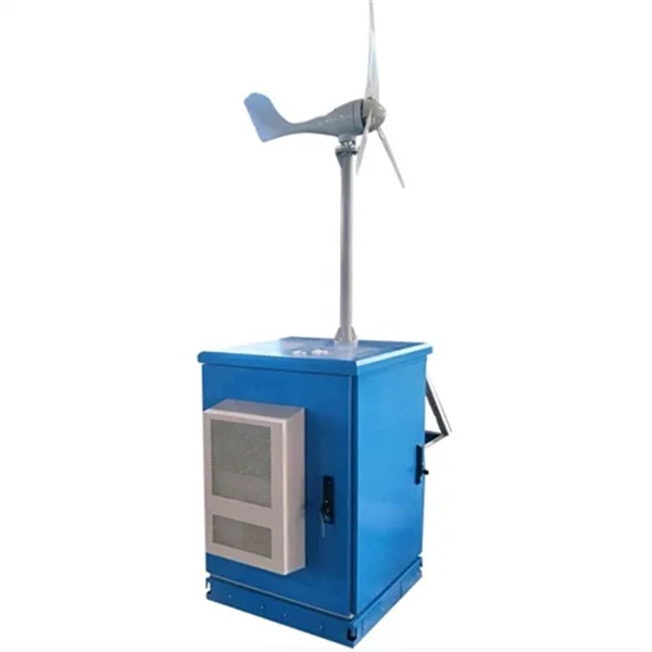
The Role of UPS Power Supplies in Industrial Control Systems
The Role of Industrial Grade UPS Systems Industrial grade UPS systems are designed to provide a continuous and stable power supply to manufacturing equipment, ensuring that operations can continue uninterrupted even in the event of a power outage or electrical disturbance. A control panel contains specific control devices in an automated system such as PLCs, HMI's, motion drives, safety sensors, network switches, among many others. Even with decentralized systems, the power source for the embedded control hardware comes from the main panel. Unlike standard UPS systems, industrial-grade units are built to. Drawing from Delta Wye Electric's 45+ years of experience installing and maintaining industrial UPS systems across manufacturing, pharmaceuticals, and critical infrastructure, this guide provides the technical insights facility managers and engineers need to make informed decisions. For facilities seeking a proven solution, the GTL33 Low Frequency Online UPS series (10–600kVA).
[PDF Version]
-
Can fiber optic cables be run alongside 35kV power cables
General Consideration: It is generally not recommended to run fiber optic cables in the same conduit as electrical power cables. This is due to several potential risks and complications that can arise from such an arrangement. When a communications cable runs parallel and in close proximity to a power cable, these magnetic fields induce unwanted currents—a phenomenon known as inductive coupling—into the sensitive data conductors. This induced noise can. TECHNICAL GUIDELINE July 30, 2020 TG030 Rev. Electrical Interference: Electrical cables can produce electromagnetic. Maintaining proper separation between power, data, and limited energy cabling is foundational to system performance, safety, and code compliance. Other than that you haven't provided much information, given. Laying network cables parallel to electrical cables is often necessary due to space constraints but comes with its own set of challenges, primarily due to electromagnetic interference (EMI).
[PDF Version]
-
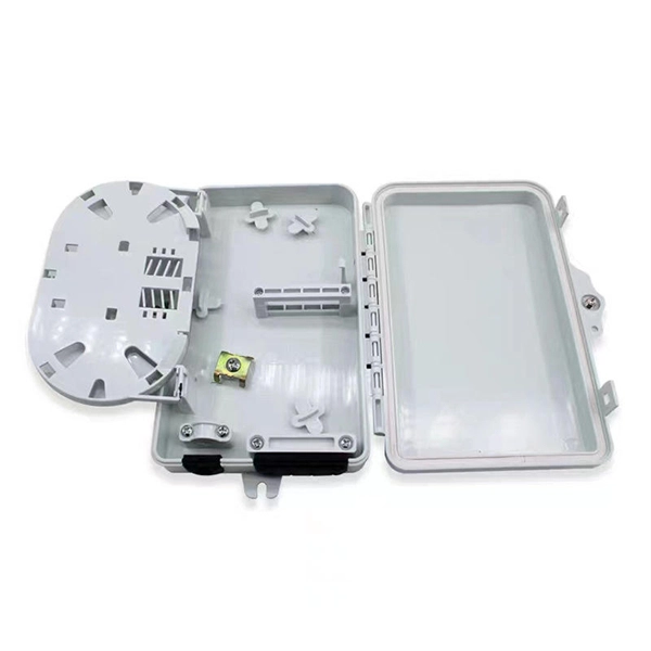
How are optical power meters classified
An optical power meter (OPM) is a device used to measure the power in an signal. The term usually refers to a device for testing average power in systems. Other general purpose light power measuring devices are usually called,, power meters (can be sensors or ), or lux meters. A typical optical power meter consists of a , measuring and display. The sens.
-
How to route fiber optic cables for high-voltage power lines
This technique takes a small, lightweight fiber optic cable and wraps it around or lashes it to the power line. The cable is called optical power attached cable (OPAC), and it is lashed to the power cable with a specialized tool that is pulled from the ground, such as a. Installing ADSS (All-Dielectric Self-Supporting) cables near live power lines demands precision, compliance with safety standards, and an understanding of high-voltage risks. This guide from GL FIBER breaks down the process into actionable steps, aligned with IEEE 524 and IEC 61935-1 protocols, to. Most aerial fiber optic cables are installed by lashing to a steel messenger wire strung between poles, but there is a category of cables with special high-strength jacket designs called all-dielectric self-supporting (ADSS) cables. ADSS cables are designed to withstand very high-tension loads. bles in a high voltage environment, with typical line voltages of 115 kV or more, requires the evaluation of certain critical parameters. Curr ntly, there are a limited number of industry documents that address the requirements for optical fiber cables near high voltage circuits.
[PDF Version]
-
How to route large power cable trays
Learn how to install cable trays for large-scale projects with our professional, step-by-step guide covering industry standards, safety protocols, and efficient routing techniques. This guide covers the critical steps, from selecting the right electrical cable tray and performing accurate cable fill. Cable tray installation implies the construction of an electric road that will be safe. The beginning of success is to review the Bill of Quantities (BOQ) so that. Cable tray systems provide a safe, organized, and flexible method for supporting insulated conductors and cables in commercial and industrial electrical installations.
-
How to pull up a power fiber optic cable
Fiber optic cables should always be pulled by the strengthened yarn fibers inside the outer jacket. This article explores recommendations for pulling and installing fiber optic cable. Most fiber optic cables boast a pull strength of 100 – 200. Fiber optic cable is surprisingly strong, durable and pliable; however, several best practices should be followed to ensure a successful cable installation. Most fiber damage does not come from normal operation after the system is live. More than half of cable problems happen because of wrong pulling. In 2025, new tools like hydraulic blowers, smart monitors, and better grips help you lower risks, save money, and keep the. A duct is available from point A to point B, a pull tape is blown in, a fiber optic cable is attached to it and the cable is pulled through the duct.
-
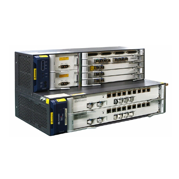
Power of Huawei optical modules
In the AI era, Huawei provides a full range of GE to 800GE optical modules, featuring three major capabilities: Spanning (ultra-long transmission), Stable (ultra-high reliability), and Secure (ultra-solid security). To address these demands, Huawei has launched the StarryLink optical module brand. This announcement occurred during the data center session titled. Describes what an optical module is and FAQs, including the fundamentals, appearance and structure, key performance counters, common types, and naming conventions of optical modules, causes of optical module failures and corresponding protection measures, types of optical modules supported by. An optical module is a component that completes electrical/optical conversion on an optical network. Huawei MA5600T series only support GPON and XG-PON; MA5800 series supports GPON, XG-PON, XGS-PON, XG-PON&GPON Combo, XGS-PON&GPON.
[PDF Version]
-
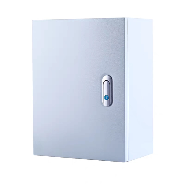
Function of the small busbar in the central power switch
The bus bar is a metal strip that distributes electrical current to the individual circuit breakers. In most assemblies you will find horizontal main bars, vertical risers, neutral and equipment-ground buses, and purpose-designed. What are Busbars, Bus Stabs, Circuit Spaces, Breaker Slots, Neutral Terminals, and Ground Terminals in an Electrical Panel or Load Center? Electric panels and load centers in residential and commercial applications have some different setting for breaker installation ad load circuit distribution. They connect directly to the main power source and are designed to handle high current loads safely. Circuit Breakers act as protective devices within the panel.
-
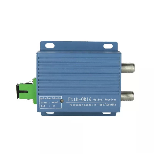
Increase the light output power of the optical module
An optical amplifier is a device which receives some input signal light and generates an output signal with higher optical power. Typically, inputs and outputs are laser beams (very rarely other types of light beams), either propagating as Gaussian beams in free space or in a fiber. At the receiver end, the optical signals are reconverted into electrical. In this guide, we will explain what optical signal strength is, how to check it on Cisco IOS using the command line, and how to troubleshoot common light level issues. Assume the. This application note gives a short introduction to optical modules and the need of an optimized power tree in them and then concentrates on the use cases and benefits of four-switch and inverting buck-boost converters inside optical modules.
-
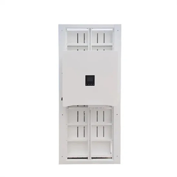
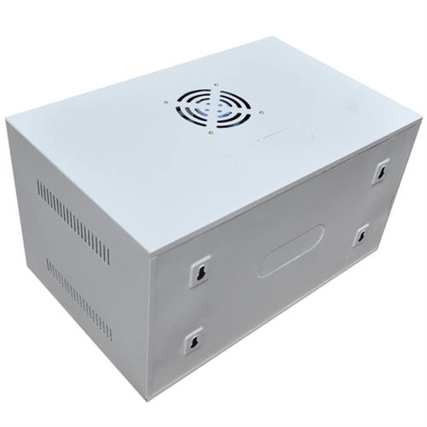
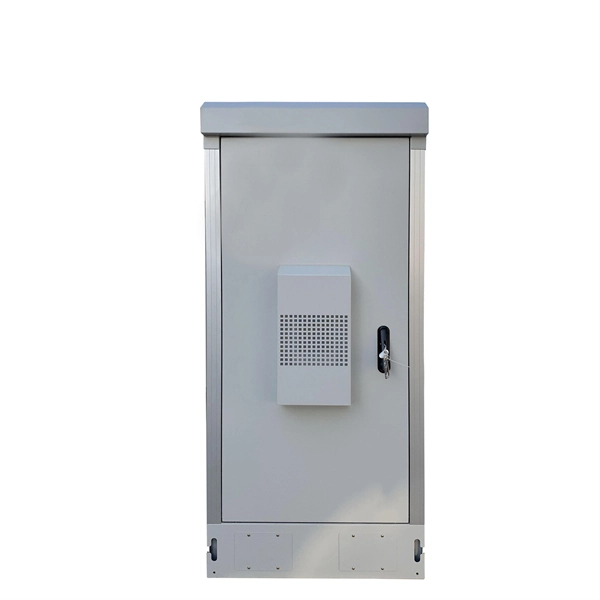
Dedicated power distribution box for engine room
Paneltronics' enclosure box-build assemblies provide efficient consolidated assembly solutions for several common functions and requirements including: 1. Ignition protection 2. Common buses 3. Control.