-
Welding of the bottom and edge of the cable tray
This short shows key steps: cutting sheet metal to size, punching or slotting for wire access, bending edges to form the tray shape, welding joints for strength, and smoothing edges for safety. Cable tray welding is essential for ensuring the structural stability of cable tray systems in industrial and commercial wiring setups. It is constructed of precision-engineered, high-quality welded steel wire and is the result of decades of research gained from the installation of over 160,000 miles of tray across the globe.
-
Cable tray horizontal tee cutting method
Completely adaptable, B-Line Flextray is designed to accommodate jobsite changes. For the best results, use a WB30BC Angular Blade Offset Bolt Cutter . to produce a clean cut. Do not use center cut style cutters, as they will leave a rough, burred cut that can damage cables and/o oximately a 45° angle. Cut the bottom wires firs in the order as shown. Flip the tray. To properly bond Hubbell ® painted cable tray, remove the plastic masking device from the trays on each end (exposing the pre-galvanized wire), and splice sections together using Hubbell ® splice kits. For cable trays that are not UL Classified as being “Suitable as an Equipment Grounding. Horizontal Tees link three 10" straight channel sections or compatible transitional fittings, enabling the creation of a sleek and efficient horizontal branch within a fiber routing system. Item code: HT Reducing Tee: W1>W2. Only two splices are required to securely connect tray widths of wire basket tray. The. Use this guide to learn the most effective installation practices when installing Cablofil tray. Engineers and contractors in North America and around the world have found.
[PDF Version]
-
Complete Guide to Cutting Inner Bends of Cable Trays
This guide explains how to make 90° bends, vertical bends, tees, and offsets in wire mesh cable trays safely and professionally. Horizontal 90° Bend (Flat Bend) 2. Cross Bend (4-Way. OTHER THAN 90 ̊ JUNCTIONS Use this guide to learn the most effective installation practices when installing Cablofil tray. Each example of bends and tee's clearly illustrate proper tray cutting combined with recommended usage of Cablofil accessories. Oglaend System manufacture and deliver Multidiscipline modular bolted support systems, cable trays, cable ladders and accessories for complete installation and containment of Instrument, Electrical, Telecom, HVAC and Piping. Hubbell Wiring Device-Kellems and Hubbell Premise Wiring are divisions of Hubbell Incorporated, a U. headquartered manufacturer with over 130 years of supplying solutions for the electrical and data markets.
[PDF Version]
-
Materials for reporting the cutting of optical cables
This includes optical loss test set (OLTS) readings, optical time-domain reflectometer (OTDR) traces, and power meter readings. For contractors and network technicians, a well-prepared report provides the proof of performance required for certification, compliance, and client handover. Meets ISO/IEC and TIA-568 standards. *ISO stands for the International Organization for Standardization, a non-governmental organization. The Contractor tasked to perform testing or splicing on any fiber optic cable will follow these testing standards to fulfill their contractual obligations. This testing. Check each product page for other buying options. Imagine trying to find a single needle in a massive haystack. What Can Happen? · Failed communications modules in the equipment Underground cable dig-ups Aerial cable damage from gunshots and a squirrel. Lets take the example below: This link has pretty much every type of event you nay expect to see.
[PDF Version]
-
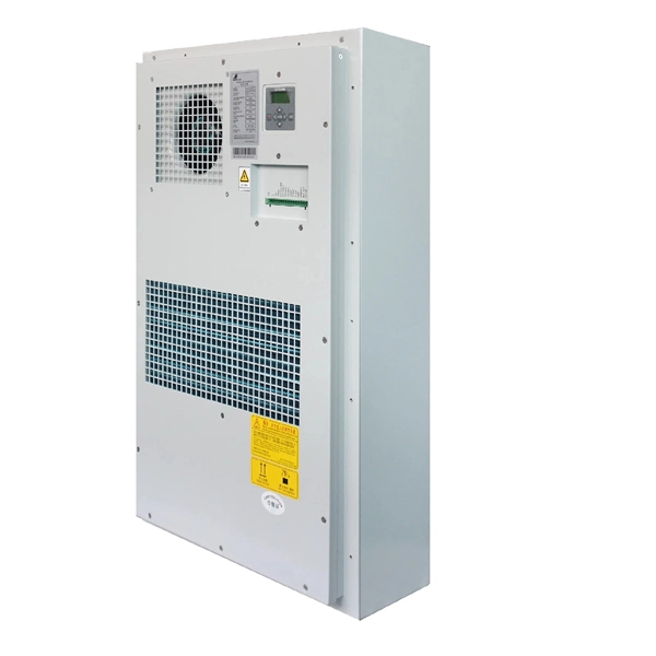
Welding grounding of distribution box
26 mm 2 (10 AWG) ground wire must be used, and in all other markets a 6 mm 2 must be used. On the US market, a 5. Grounding of electrical circuits is a safety practice that is documented in various codes and standards. Applying and maintaining proper grounding methods within the welding area is important to promote electrical safety in the. Grounding is a mechanism to protect distribution equipment and people under normal operating conditions, abnormal operational (overcurrent and overvoltage) responses, and hazardous conditions such as shocks. Each DISTRIBUTION BOX and controller must be grounded. When you don't have a good ground, you don't have a suitable circuit, and your welds are always going to be. The grounding system provides a low-impedance path for fault current and limits the voltage rise on the normally non-current-carrying metallic components of the electrical distribution system. Whether you're a seasoned pro or just starting out, this comprehensive guide will give you practical.
[PDF Version]
-
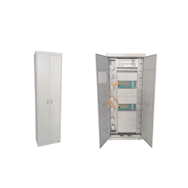
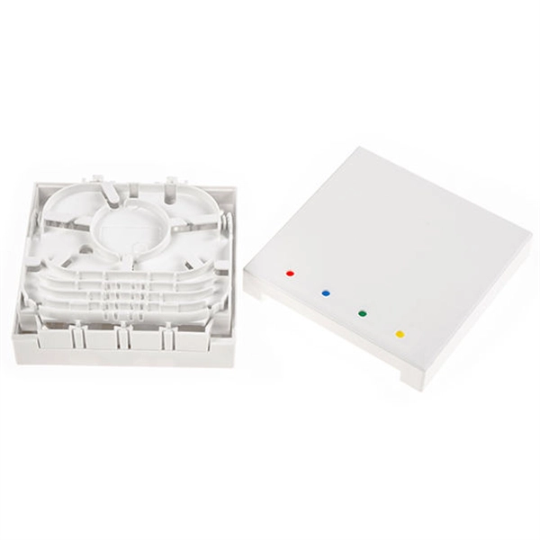
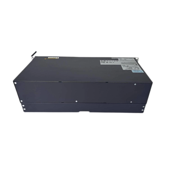
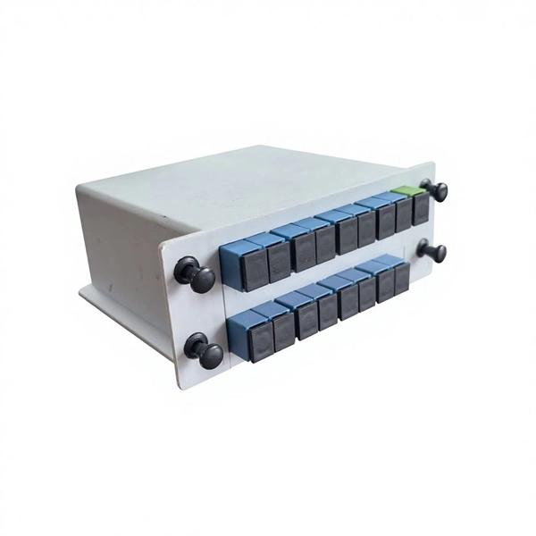
Are fiber optic splice closures useful and safe
Fiber optic splice closures keep your network safe from water, dirt, and harm. Pick strong materials and tight seals to keep signals clear., FTTH, FTTP, FTTM), splicing is essential for extending cables, repairing breaks, or connecting backbone and distribution lines. They are engineered systems designed to protect fiber splices from mechanical stress, environmental exposure, and long-term performance. Inline closures are used in applications where two identical cables are spliced and an inline closure saves space or when making repairs to damaged cables. It is an essential component that provides protection and organization for fiber optic splices, ensuring the integrity and reliability of the network. The splicebox plays a vital role in maintaining the integrity.
-
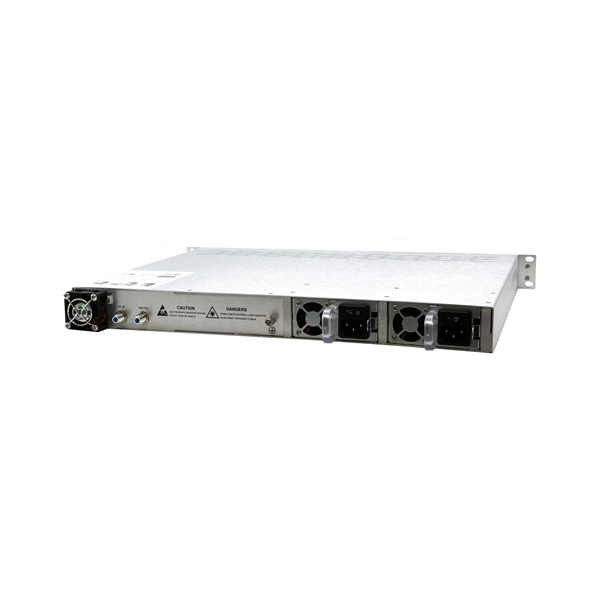
Small busbar acceptance standards and procedures
This article details the comprehensive standards for installing and inspecting busbars, including support brackets, insulators, and bus duct systems. You'll learn essential guidelines and. For complete safety instructions and precautions, always refer to the test equipment instruction manual. This approach is applicable to all types of metal enclosed busbar. Check for physical damage/defects. Check the bus arrangement to ensure that it is consistent with the approved plans. Compliance with recognized quality standards ensures electrical safety, reliability, and regulatory acceptance, especially for telecom, data centers, and industrial electrical applications. Buyers often. IEC 61439 is a standard developed by the International Electrotechnical Commission (IEC) that covers design verification for low-voltage electrical products and assemblies. Main keywords for this article are Bus Bars and Bus Ducts Design Requirements, ANSI C37.
[PDF Version]
-
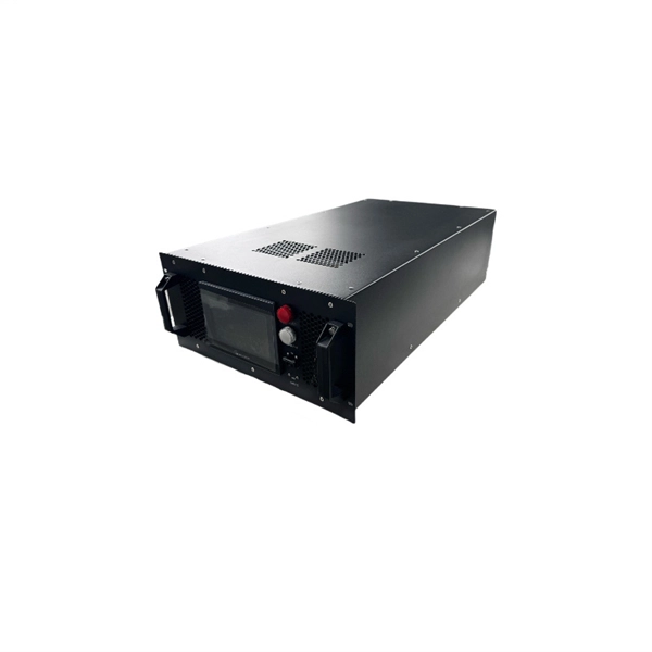
Three operating states of relay protection
Several operating coils can be used to provide "bias" to the relay, allowing the sensitivity of response in one circuit to be controlled by another. Various combinations of "operate torque" and "restraint torque" can be produced in the relay.OverviewIn, a protective relay is a device designed to trip a when a is detected. The first protective relays were electromagnetic devices, relying on coils operating on moving par. Electromechanical protective relays operate by either, or. Unlike switching type electromechanical with fixed and usually ill-defined operating voltage thresholds. Electromechanical relays can be classified into several different types as follows: "Armature"-type relays have a pivoted lever supported on a hinge or knife-edge pivot, which carries a moving contact. These relays may.