-
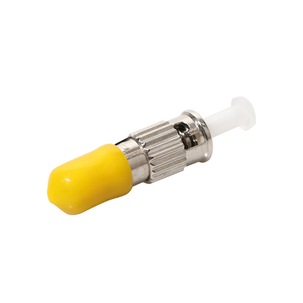
How are optical power meters classified
An optical power meter (OPM) is a device used to measure the power in an signal. The term usually refers to a device for testing average power in systems. Other general purpose light power measuring devices are usually called,, power meters (can be sensors or ), or lux meters. A typical optical power meter consists of a , measuring and display. The sens.
-
Light collection power of the second-stage beam splitter
It is currently used in modern three-CCD cameras. An optically similar system is used in reverse as a beam-combiner in three- LCD projectors, in which light from three separate monochrome LCD displays is combined into a single full-color image for projection.OverviewA beam splitter or beamsplitter is an that splits a beam of into a transmitted and a reflected beam. It is a crucial part of many optical experimental and measurement systems, such as In its most common form, a cube, a beam splitter is made from two triangular glass which are glued together at their base using polyester,, or urethane-based adhesives. (Before these synthetic,. Beam splitters are sometimes used to recombine beams of light, as in a. In this case there are two incoming beams, and potentially two outgoing beams. But the amplitudes.
-
How to use a red light power meter
Lets say you are a light therapy enthusiast that wants to take your own proper measurements. Or you bought a red light therapy product and want to verify it meets outputs the intensity that it claimed. Then.
-
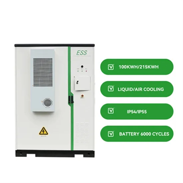
DC busbar power failure
If the busbar protection fails to trip when an external fault occurs or if it falsely trips while in use, the power system could become unstable. A total power outage will result from this. Regular dielectric testing is crucial to verify the quality of insulation and ensure that busbars can perform reliably under both normal. Busbar insulators are the backbone of electrical systems, ensuring safe power distribution by isolating conductors and preventing faults. However, harsh operating conditions, material degradation, and improper maintenance can lead to insulator failures—jeopardizing safety and system reliability. The DC-link capacitor selection is one of the first and most important steps. Consequently, power busing design needs critical consideration in terms of performance under converter operation, asymmetric loading, short-circuits, thermal and insulation breakdown.
[PDF Version]
-
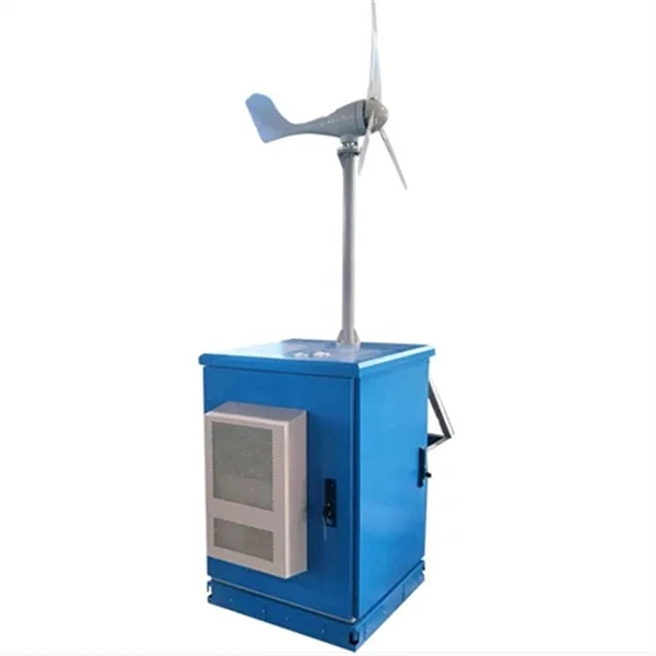
Anti-residual power systems for wind power generation
A hybrid wind-solar energy system consists of the following components: 1. Solar panels 2. Wind turbine – see our guide to the best wind turbines 3. Charge controller 4. Battery bank 5. Inverter 6. Power dis.
-
How to route large power cable trays
Learn how to install cable trays for large-scale projects with our professional, step-by-step guide covering industry standards, safety protocols, and efficient routing techniques. This guide covers the critical steps, from selecting the right electrical cable tray and performing accurate cable fill. Cable tray installation implies the construction of an electric road that will be safe. The beginning of success is to review the Bill of Quantities (BOQ) so that. Cable tray systems provide a safe, organized, and flexible method for supporting insulated conductors and cables in commercial and industrial electrical installations.
-
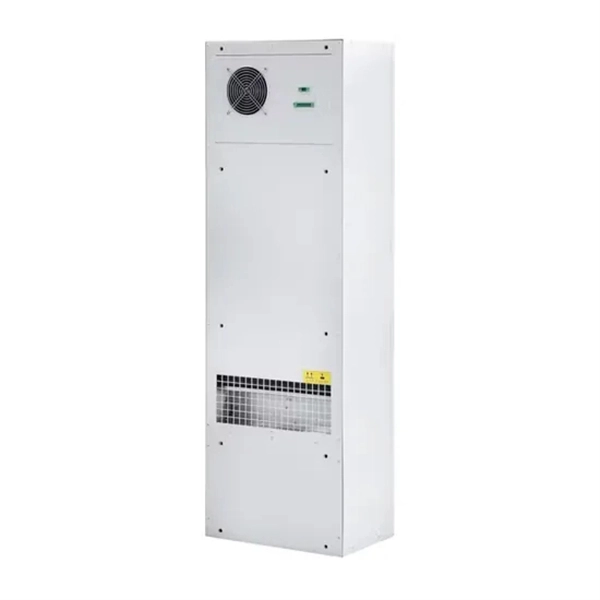
Increase the light output power of the optical module
An optical amplifier is a device which receives some input signal light and generates an output signal with higher optical power. Typically, inputs and outputs are laser beams (very rarely other types of light beams), either propagating as Gaussian beams in free space or in a fiber. At the receiver end, the optical signals are reconverted into electrical. In this guide, we will explain what optical signal strength is, how to check it on Cisco IOS using the command line, and how to troubleshoot common light level issues. Assume the. This application note gives a short introduction to optical modules and the need of an optimized power tree in them and then concentrates on the use cases and benefits of four-switch and inverting buck-boost converters inside optical modules.