-
Microcomputer Testing of Relay Protection
For testing high-voltage microcomputer protection devices, it is recommended to use a microcomputer relay protection tester capable of simultaneously outputting three-phase voltage and three-phase current, and equipped with timing function for digital inputs. Meet all test requirements on site. It can test not only various traditional relays and protection devices, but also various modern microcomputer protections, especially for transformer differential protection and. Protective Relay Test Set, Relay Tester, Secondary Current Injection Test Kit, Microcomputer Protection Testing, 3-Phase Relay Tester Discover why selecting the right Protective Relay Test Set is critical for microcomputer protection verification. In this paper, the characteristics of the equipment itself and the external environment are comprehensively considered, and.
[PDF Version]
-
Internal relays of relay protection devices
The fault can be located upstream or downstream of the relay's location, allowing appropriate protective devices to be operated inside or outside of the zone of protection.OverviewIn, a protective relay is a device designed to trip a when a is detected. The first protective relays were electromagnetic devices, relying on coils operating on moving par. Electromechanical protective relays operate by either, or. Unlike switching type electromechanical with fixed and usually ill-defined operating voltage thresholds. Electromechanical relays can be classified into several different types as follows: "Armature"-type relays have a pivoted lever supported on a hinge or knife-edge pivot, which carries a moving contact. These relays may.
-
Intermediate relays are commonly used in relay protection
Intermediate relay: used in relay protection and automatic control systems to increase the number and capacity of contacts. Its main function in an electrical control system is to carry. What is an Intermediate Relay? The intermediate relay is a low-power device for activating higher-power circuits. We can also call it an interposing relay. Depending on the application—whether for signal amplification, overload protection, safety shutdown, or high-frequency switching —different types of relays are used.
-

Analysis of the Four Characteristics of Relay Protection
The article first analyzes the role, composition, requirements of relay protection, and then analyzes the fault analysis of power system protection and treatment measures; the final analyzes the question of the relay protection substation operation. (1) Selectivity: refers to that when the Electrical fault occurs, the relay protection device acts and only removes the fault element. Minimize the scope of power outages as much as possible to continue the operation of non faulty parts of the system. Divide into main protection and backup. To provide effective and reliable protection to the power system, a protective relay must have the following essential functional characteristics: Selective, Fast, Stable, Reliability, Sensitivity, Simple Construction and Installation Mechanism, and Cost-effective. These are some essentially. Protective Relays - Technical Seminar Nov 2016 - Copyright: IEEE 2 Abstract: Protective relays and devices have been developed over 100 years ago to provide “lastline”of defense for the electrical systems. Therefore, the whole system has gone down, even though many circuit breakers have remained closed.
[PDF Version]
-
Relay protection function of the main switch
A protective relay is an automatic device that detects abnormalities in an electrical circuit and closes its contacts. This action completes the circuit breaker 's trip coil circuit, causing the breaker to trip and disconnect the faulty section from the healthy circuit. First, relays were used as signal repeaters within long-distance. Fingrid's application guideline for relay protection presents the operating principles of the relay protection in Fingrid's 110, 220 and 400 kV power networks and the requirements for operation of the protection systems of Fingrid customers (hereinafter referred to as 'customer'). The application. Provides protection, logic, and metering All-in-one solution. Three fundamental components required for each circuit breaker. While this is bad, It's not a.
-
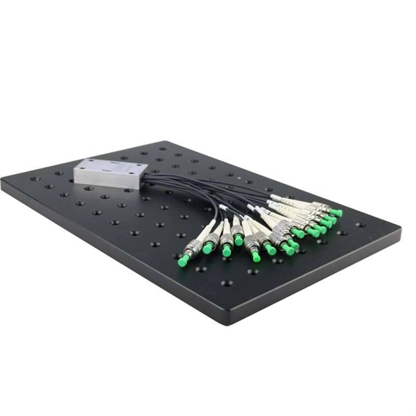
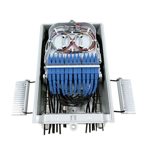
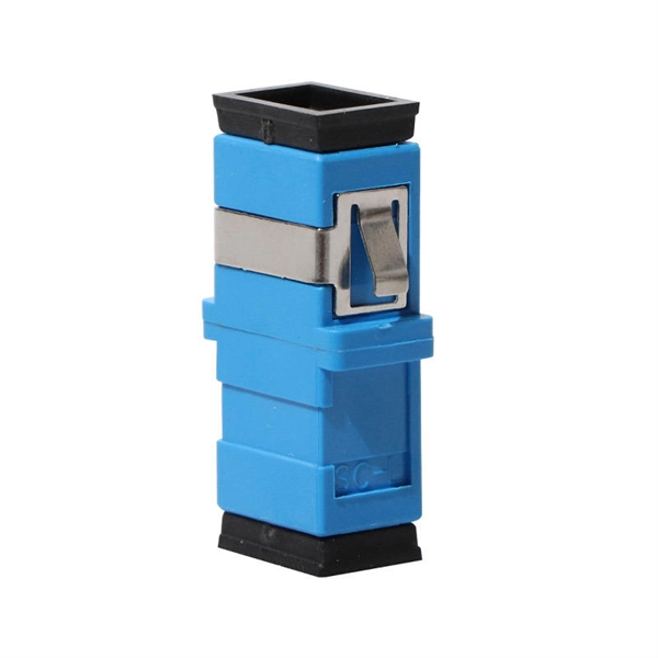
Optical cable protection structure includes
Optical fibers have small cross sectional areas. Cable structure includes buffers, strength members, and jackets. What are fiber optic cables made of? A fiber optic cable consists of five basic components: the core, the cladding, the coating, the strengthening fibers, and the cable jacket. When searching for a fiber optic cable, we need to pay attention not only to the connectors, such as SC to ST fiber cable. An optical fiber cable is a complex structure designed to protect fragile glass fibers that transmit digital data using light signals. This advanced cabling solution allows fast, secure data transfer and telecom over long distances. This course describes multimode and single mode step-index and graded-index fibers. Cable provides protection for the optical fiber or fibers within it appropriate for the environment in which it is installed. You will also learn how different aspects of the product can affect budget and design.
[PDF Version]
-
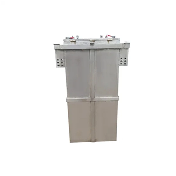
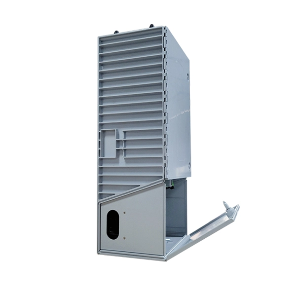
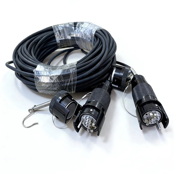
Distribution Box Protection Method
Its primary purpose is to ensure safe and efficient power distribution while providing protection via fuses or circuit breakers against overloads and short circuits. Distribution boxes are built with durable materials, typically metal or high-grade plastic, designed to endure. EPRI has been exploring protective device configuration approaches tar-geted at minimizing the chances of adverse interactions with the power system and the environment. More specifically, electrical faults caused by vegetation, animals, conductor slap, lightning and equipment failures can each. A distribution box, also known as a power distribution box or electrical distribution box, is used to distribute electrical power safely to multiple circuits. Circuit Breakers or Fuses: These safety devices automatically stop the flow of electricity during faults or overloads. Fuses melt when too much current. Electrical systems power our homes, offices, and industrial facilities, but behind every reliable electrical setup lies a crucial component that often goes unnoticed: the distribution box.
[PDF Version]