-
Huawei optical modules are compatible with 10 Gigabit and 1 Gigabit speeds
31 Gbps data rate and such applications as 10G Ethernet (10. SFP+ Double Fiber optical transceiver is multi-purpose module used in number of different places of today's networking. Huawei is not liable for any problem caused by the use of non-certified optical or copper. Huawei compatible SFP+10GE-LH10-SM1310 (02311MUU) is SFP+ (Small Form factor Pluggable) Transceiver, operating over Double Fiber Single-Mode Fiber (SMF) optical cable. In today's fiercely competitive environment, people's demands for quality are increasing. The primary difference is that SFP+ is an updated version of SFP but supports higher speeds up to 10Gbps. If the SFP-10G-ER-1310 is connected. Can 1G SFP optics work with 10Gb SFP+ ports on a 10Gb switch, or vice versa? This comprehensive guide reveals the intricacies of SFP and SFP+ compatibility and provides useful solutions for network switch users.
[PDF Version]
-
Working principle of 10 Gigabit fiber optic patch cord
The functioning of a fiber optic patch cord relies on its construction. It consists of a core with a high refractive index, enveloped by a coating featuring a lower refractive index. This assembly is fortified using aramid yarns and encased within a protective jacket. These cables, also known as fiber optic patch cables or jumpers, are designed to transmit information as pulses of light, offering unparalleled speed, bandwidth, and immunity to electromagnetic interference compared to traditional copper cables. As network demands continue to explode, selecting the. Key factors to consider in the design of 10 Gigabit Ethernet networks are: The network topology, including operating distances, splice losses and numbers of connectors (i. Fiber optic patch cables are found almost everywhere; cable television networks (CATV), data centers, computer networks, and telephone networks.
[PDF Version]
-
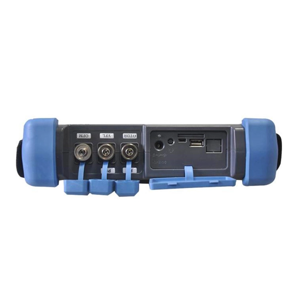
How to connect the 10 Gigabit Ethernet cable to the fiber-to-electrical port module
A special 10G Copper RJ-45 Transceiver (10G-SFP-T) is required to connect the SFP+ port to RJ45. It allows connecting a server/storage side Cat6/7 cable to an SFP+ port transceiver. An SFP module (or optical transceiver) converts electrical signals from network devices (switches, routers) into optical signals for fiber transmission and vice versa. 1G/10G SFP+: Standard for Gigabit and 10 Gigabit Ethernet. These transceiver modules are hot-swappable input/output (I/O) devices that plug into 100BASE, 1000BASE and 10GBASE ports (for SFP+), which connect the module port with the fiber-optic or copper network. 4ft (30m) * using Cat6a/Cat7 or above cable for 10G connection in various applications. In this video, we'll guide you through building a high-speed 10G LAN by connecting two fiber switches. Finally, check the transmit (TX) and receive (RX) paths to ensure that signals are aligned.
[PDF Version]
-

Switches are all 10 Gigabit optical
To implement different 10GbE physical layer standards, many interfaces consist of a standard socket into which different physical (PHY) layer modules may be plugged. PHY modules are not specified in an official standards body but by (MSAs) that can be negotiated more quickly. Relevant MSAs for 10GbE include (and related X2 and XPAK), and. When choosing a PHY.
-
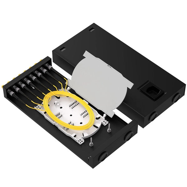
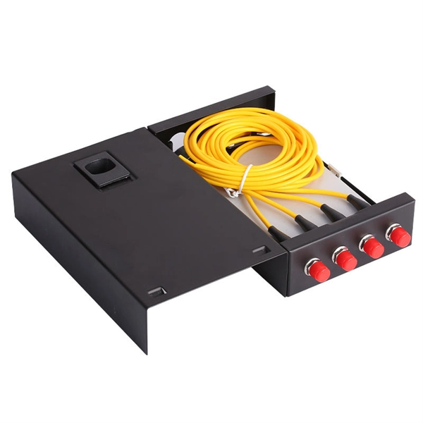
Fixing bracket on the back of the distribution box
How to install the mounting bracket? Many engineers don't know how to install this accessory. With the latest design, it can be confusing. Mounting bracket is a flexible structure, which makes it easy to adjust or replace the electrical components. All the components, wires and connections are under the protective cover due to the same height. The BBT-HF telescoping bracket, used with the BBA and BBA-4 box mounting brackets, provides an extremely flexible, fast rough-in solution. more Charlie DIYte (CharlieDIYte) tagged products below. Make sure the walls are strong enough to bear the weight of the box and electrical equipment. Ground. Electrical box screw mounts broke, can it be fixed without tearing up wall? I was unplugging an appliance in the kitchen when the whole outlet pulled out of the wall. Second photo shows my temp.
-
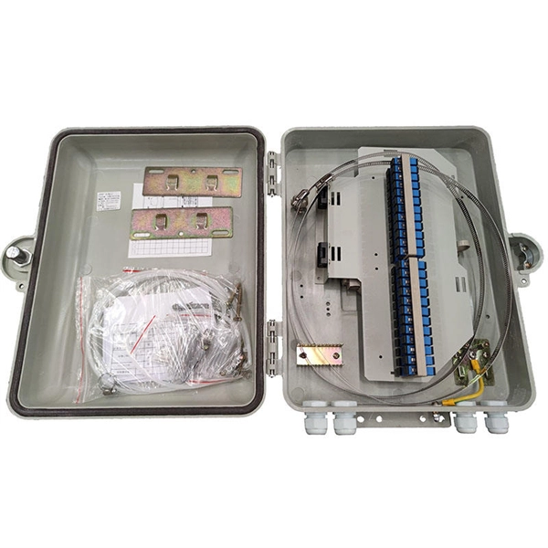
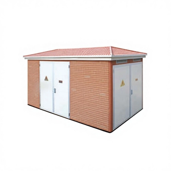
Research and Development of Intelligent Distribution Box Technology
This paper describes the design, development, and deployment of a smart distribution box enabled by the Internet of Things (IoT) with the goal of improving defect detection, power monitoring, and overall energy management in single-phase residential power applications. The main purpose of this work is to realize a low-voltage electrical distribution panelboard that allows for real-time load. The intelligent distribution box comprises multiple electrical devices, the electrical devices at least comprising a common power supply module, a main input intelligent circuit breaker, at least one branch intelligent circuit breaker, a central processing unit, and a standard guide rail. The. In order to improve the operational safety and market operation efficiency of the prosumer energy community, to achieve comprehensive monitoring of abnormalities, fault alarms, and intelligent control and maintenance, to reduce the risk of information security, and to address the many types of.
[PDF Version]
-
Principle of Grounding Wire in Home Electrical Distribution Box
The ground wire working principle is based on providing a low-resistance path for fault current to flow safely into the earth. Electricity always follows the path of least resistance. Grounding ensures that fault current prefers the ground path instead of passing through the human. Whether you're a seasoned pro or just starting out, this comprehensive guide will give you practical insights into proper grounding techniques, with a special focus on how selecting quality materials from a reliable building material supplier impacts your entire system's safety and longevity. Installed correctly, grounding wire can prevent electrical shocks or fires at homes or in offices. It. Publish Time: 03/10 2025 Author: Site Editor Visit: 969 The correct connection method of Distribution box grounding wire mainly includes the following steps: 1. The ground wire. Grounding means connecting to the Earth or extending the ground connection to other things in your home, such as the metal frames and components of electrical equipment, wiring, appliances, light fixtures and receptacles — even if they're far away from the actual ground. Establishing a connection.
[PDF Version]
-

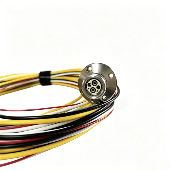
Grounding of anti-slide pile distribution box
Attach a ground wire from one of the threaded studs (A) at the bottom of the housing, to the mounting plate (B). The ground resistance between all system parts shall be <. Power from factory ground must be installed by a qualified electrician. Each DISTRIBUTION BOX and controller must be grounded. 26 mm 2 (10 AWG) ground wire must be used, and in all other markets a 6 mm 2 must be used. Following its application, various structures have been developed. One path is aimed at improving the. Anti-slide piles are structural elements inserted into stable strata below potential sliding surfaces to counteract landslide thrust through anchorage effects. Widely used in slope reinforcement, landslide stabilization, bridge abutments, and tunnel reinforcement projects, these piles offer. violation, and misinterpretation. The piles usually have a large ide piles, should meet several conditions. If the anti-slide pile intersects into the assessed slip surface, then for the calculation of the factor of safety is introducing passive (resisting) force P which corresponds to bearing capacity of pile Vu.
[PDF Version]
-
Is the grounding of the distribution box considered repeated grounding
Grounding in buildings and connecting the neutral line to the distribution or control panels' grounding device is also called repeated grounding. Correct grounding of services depends upon understanding the definition and role of the grounded conductor. The neutral conductor is typically the grounded conductor connected to the system's neutral point, carrying current under normal operation. 4 (A) (1) states that grounded electrical systems “shall be connected to earth in a manner that will limit the voltage imposed by lightning, line surges, or. While there are other types of grounding like repeated grounding, lightning protection grounding, and electrostatic shielding grounding, their functions align with these two purposes. To catch up on Lorenzo Mari's series on National Electrical Code 2023 Basics: Grounding and Bonding, follow these links: NEC's Section 250.
[PDF Version]
-
Can grounding be done outside the distribution box
As for your title question: yes, it's sufficient to ground an outlet only to its box -- if, and only if, the box itself is properly grounded. Metal boxes are grounded whenCorrect grounding of services depends upon understanding the definition and role of the grounded conductor. The neutral conductor is typically the grounded conductor connected to the system's neutral point, carrying current under normal operation. Grounding electrode conductors must be connected at. Today, we're diving deep into the world of distribution box grounding, breaking down the standards, and shining a light on those sneaky mistakes that even experienced electricians sometimes make. Code Change Summary: Clarifications were made regarding the connection of equipment grounding conductors in a box. Why was this so common? What the the thinking in doing it this way? This is. For one thing, the conductors are passing through box mounting holes! That particular kind of conductor belongs in conduit, which should be entering through one of the circular knock-out holes in the box. Check your local electrical codes and schedule inspections.
[PDF Version]