-
GYXTW optical cable 1550 has high attenuation
The attenuation in the 1550nm window is 0. 652A⁄B is the basic. In fiber optics, the choice of wavelength is a fundamental design decision: it determines how far your signal can travel, how much it attenuates, and how many channels you can multiplex. GYXTW fiber optic cable is constructed by. GYXTW is a single loose tube steel tape armored fiber optic cable designed for outdoor use. It is ideal for aerial or ducted installations, providing reliable communication in metropolitan networks, access networks, and inter-office connections. (Dimensions of cable constructions) 5. Intrinsic: Electronic/atomic resonances in SiO₂. Macrobends: Visible light leakage (sharp bends).
-
Bosnian transparent optical cable is resistant to high temperatures
The full realisation of optical fibres in devices such as sensors is reliant on the stability of their polymer coating under in-service conditions. Depending on the application, resistance to several environmental f.
-
What is the maximum speed of the optical module
6T transceiver is an optical module designed to handle data transmission at a speed of 1. These modules, including SFP, SFP+, and SFP28, are widely used in enterprise networks, data centers, and carrier-grade deployments. Lanbras Optical Module and Cable solutions cover up to 800G, 1. Our products ensure low latency, high. As data center speeds increase, the reliability and power efficiency of the SFP optical module become paramount, directly impacting overall system thermal management and uptime. A robust optical backbone is only as strong as the transceivers linking the components. Key characteristics include: Speed: 1 Gbps, 10 Gbps, 25 Gbps, or higher. It uses 8 electrical lanes, each.
-
Selection Guide for OSFP and QSFP Optical Modules Used in Supercomputing Centers
This article compares OSFP and QSFP-DD in terms of physical dimensions, power and thermal characteristics, and compatibility, providing practical guidance for data center and network infrastructure planning. In the rapidly evolving landscape of high-performance computing and AI infrastructure, NVIDIA optical transceivers have emerged as critical components for enabling next-generation 800G network deployments. This guide gives you the complete picture. Our study of OSFP transceiver technology will begin with basic concepts and continue until we reach advanced technical. Today's mainstream 400G optical modules use three primary form factors: QSFP-DD, OSFP, and QSFP112. This article provides a comprehensive comparison of the three. In 2025, the optical transceiver market has shifted decisively. On the path to the 400G era, different form factors act as distinct engines, delivering.
[PDF Version]
-
Selection Guide for QSFP Active Optical Modules for Cloud Computing
This QSFP module guide delivers a technical deep dive into the most prevalent QSFP transceivers, their specs, real-world deployments, and practical buying advice. Whether you're upgrading to 100G or optimizing your 40G links, this article is tailored for network architects, engineers, and system. The Ultimate Guide to QSFP Optical Modules: 40G to 800G Interconnect Evolution In today's digital era sweeping across the globe, data centers—the core hubs of information processing—have an insatiable demand for high-speed, high-density data transmission solutions. By increasing channel density, it enables higher port utilization and seamless upgrades on existing infrastructure. As a core component of high-speed networks, QSFP-DD. As high-speed networks continue to evolve, optical transceivers like QSFP-DD, QSFP28, QSFP56, SFP56, and SFP28 have become the core components enabling scalable and efficient connectivity across data centers and telecom environments. Below is a detailed breakdown of each module series.
[PDF Version]
-
Optical module receiving sensitivity is less than
Receive sensitivity defines the minimum optical power required to maintain an acceptable bit error rate (BER ≤ 1E-12) at specific data rates. It's a core parameter in optical transceiver specifications, indicating the module's capability to detect weak incoming signals. What Is BER? The bit error rate (BER) measures the data transmission precision within. In optical communication systems, sensitivity is a measure of how weak an input signal can get before the bit-error ratio (BER) exceeds some specified number. For example, SONET specifies that the BER must be 10 -10 or better. This level must fall within the receiver's power range.
-
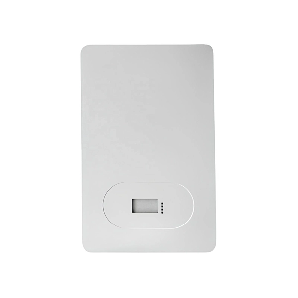
Armenia Passive Optical Network Low Voltage Circuit
INCRIPT provides project development and management, turnkey solution implementation, installation, commissioning, and technical maintenance of low-voltage systems. The Relevance Inspector will open in the Coveo Administration Console. Our integrated circuits and reference designs help you create optical network terminal (ONT) units that enable high-speed data connections for today's passive optical networks. Use the resources below to design a system with our. INCRIPT emerges as a proficient systems integrator with over a decade of extensive experience in the Armenian market. Since its inception, the company has continuously evolved, refining its expertise in designing, building, and upgrading IT infrastructure and engineering systems. We offer turnkey. This paper presents the design and implementation of a passive optical network (PON) based on a gigabit-capable passive optical network (GPON) standard to deliver fiber-to-the-home (FTTH) services in a small-town setting. 5% of people in rural areas have access to the Internet, but only 73. The construction and deployment.
[PDF Version]
-
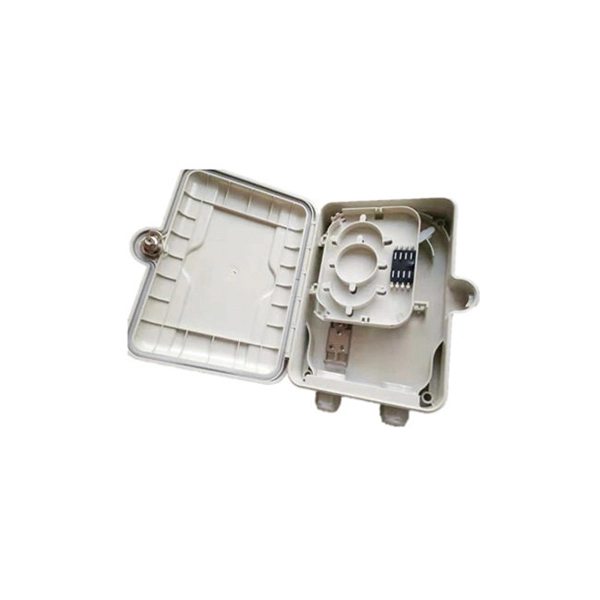
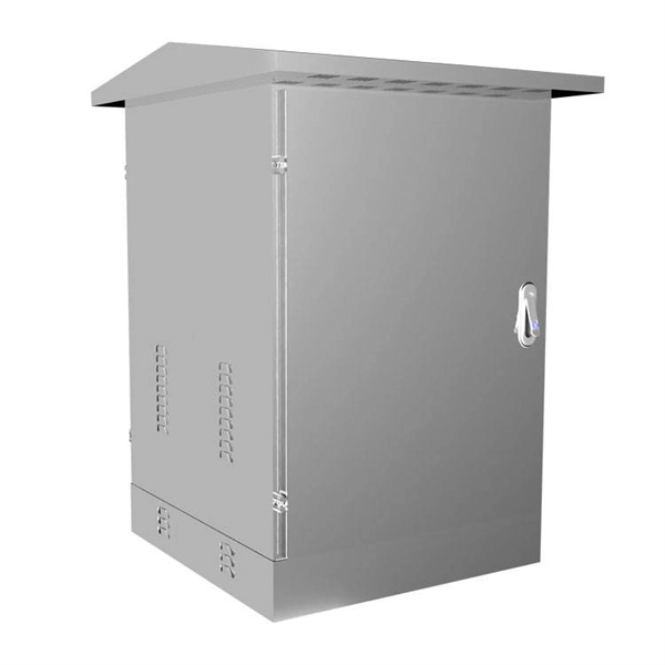
Composition of optical distribution box
It is widely adopted in FTTx cabling for both fiber cabling, provides the connection between fiber optic cables and passive optical splitters. Fiber Distribution box contains the shell, the internals (supporting frame, set fiber disc, fixing device) and optical fiber. The fiber distribution box, a crucial component in optical fiber networks, serves a dual purpose of managing and protecting optical fibers while facilitating their efficient distribution. Whether you're building a central office, data center, or FTTx distribution network, understanding the right ODF. ication and relevant standards over the range of optical wavelengths from 1260nm to 1625nm. However, component desi n should also take account of future requirements to extend operating wavelength to 1675nm. Cross-con-nections and direct connection can be two ways to.
[PDF Version]
-
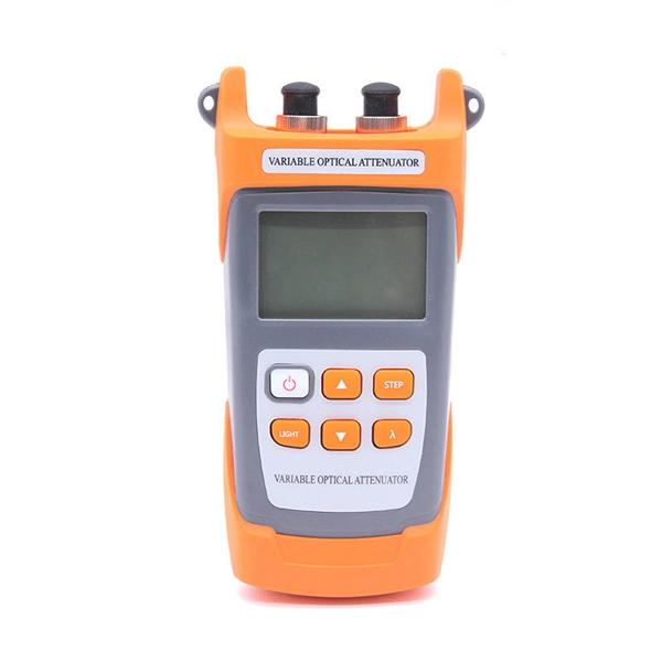
How to determine light attenuation of red light using an optical power meter
Optical attenuation compares input and output power on a logarithmic scale. When powers are in linear units, the loss in decibels is: Attenuation (dB) = 10 × log10 (Pin / Pout) If the link length L is provided, the attenuation coefficient is: Coefficient (dB/km) =. Analyze optical power drop across fibers and links. Switch units, lengths, and calculation modes easily. Needed when attenuation is an. Optical power, required for measuring source power, receiver power and, when used with a test source, loss or attenuation, is the most important parameter and is required for almost every fiber optic test. Backscatter and wavelength measurements are the next most important and bandwidth or. Optical power meters are a key element in the optimization and maintenance of such optical networks and of their components. But, for designers, just starting to work in the fiber-optic design space, measuring attenuation can seem like a monumental task.
[PDF Version]
-
The function of optical cable coiling
The coiling system must maintain balanced tension, consistent feed speed, and smooth direction transitions. The modern coiler uses a wire arrangement tool to ensure perfect layering—each loop sits exactly beside the previous one, maintaining the coil's structure. The modern fiber optic cable is the backbone of global communication networks, connecting continents through vast data highways. Today's automatic winding tools have. Fiber optic cable filling compound is not ordinary “grease” or “petroleum jelly,” but rather a semi-transparent paste-like functional material composed of base oils, thickening systems, water-blocking components, antioxidant systems, and other materials. The cable coiling and reserving device has a simple structure, offers convenient assembly and use, and can avoid accidental pull-out of a coiled and stored cable caused by. The CableCoiler 1300 is a standalone, fully synchronized high performance cable coiler for Schleuniger cut and strip machines. Often, coils are made with a.
[PDF Version]
-
How to locate the fault point in a communication optical cable
Struggling to identify faults, validate polarity or ensure quality mechanical connector terminations in your fiber optic cables? Visual Fault Locators (VFLs) are a valuable tool that make troubleshooting fast and efficient. Let's dive into everything you need to know about mastering VFLs. Common Indicators of a Cable Break Signal Loss or Interruption: If data transmission is interrupted, it could indicate a break or severe bend. Physical. Finding a fiber fault typically involves the following steps: 1. However, physical damage can disrupt this infrastructure and cause significant network issues. When fiber cables sustain damage, specialized repair techniques help. To ensure the quality and continuity of fiber optic services, it is essential to identify and locate fiber optic cable faults as quickly and accurately as possible.