-
Microcomputer Testing of Relay Protection
For testing high-voltage microcomputer protection devices, it is recommended to use a microcomputer relay protection tester capable of simultaneously outputting three-phase voltage and three-phase current, and equipped with timing function for digital inputs. Meet all test requirements on site. It can test not only various traditional relays and protection devices, but also various modern microcomputer protections, especially for transformer differential protection and. Protective Relay Test Set, Relay Tester, Secondary Current Injection Test Kit, Microcomputer Protection Testing, 3-Phase Relay Tester Discover why selecting the right Protective Relay Test Set is critical for microcomputer protection verification. In this paper, the characteristics of the equipment itself and the external environment are comprehensively considered, and.
[PDF Version]
-
What s a good major to study in relay protection
According to the education requirements for protective relay technicians, the best college majors include Electrical Engineering, Industrial Technology, and Electrical Engineering Technology. This specialized role combines hands-on technical skill with a deep understanding of. The primary goal of this paper is to recog-nize the importance of education and the training of fu-ture protection engineers, and, secondly, to suggest course content needed to meet this challenge. They focus on the system protection and control of substation equipment.
-

Analysis of the Four Characteristics of Relay Protection
The article first analyzes the role, composition, requirements of relay protection, and then analyzes the fault analysis of power system protection and treatment measures; the final analyzes the question of the relay protection substation operation. (1) Selectivity: refers to that when the Electrical fault occurs, the relay protection device acts and only removes the fault element. Minimize the scope of power outages as much as possible to continue the operation of non faulty parts of the system. Divide into main protection and backup. To provide effective and reliable protection to the power system, a protective relay must have the following essential functional characteristics: Selective, Fast, Stable, Reliability, Sensitivity, Simple Construction and Installation Mechanism, and Cost-effective. These are some essentially. Protective Relays - Technical Seminar Nov 2016 - Copyright: IEEE 2 Abstract: Protective relays and devices have been developed over 100 years ago to provide “lastline”of defense for the electrical systems. Therefore, the whole system has gone down, even though many circuit breakers have remained closed.
[PDF Version]
-
Calculation of State Grid Relay Protection
Use this Protection Relay Setting Calculator to calculate pickup current, time multiplier settings (TMS), operating time, coordination time interval (CTI), and plug setting multiplier (PSM) using fault current, CT ratio, and IEC 60255 curve parameters. To adapt the grid to the requirements of intelligentization and the dispatching and control cloud technology route, this paper proposes a relay protection setting calculation method for power grid based on distributed parallel computing. These calculations are critical in industrial. The selected protection principle affects the operating speed of the protection, which has a significant im-pact on the harm caused by short circuits. The faster the protection operates, the smaller the resulting ha-zards, damage and the thermal stress will be.
-
Relay protection function of the main switch
A protective relay is an automatic device that detects abnormalities in an electrical circuit and closes its contacts. This action completes the circuit breaker 's trip coil circuit, causing the breaker to trip and disconnect the faulty section from the healthy circuit. First, relays were used as signal repeaters within long-distance. Fingrid's application guideline for relay protection presents the operating principles of the relay protection in Fingrid's 110, 220 and 400 kV power networks and the requirements for operation of the protection systems of Fingrid customers (hereinafter referred to as 'customer'). The application. Provides protection, logic, and metering All-in-one solution. Three fundamental components required for each circuit breaker. While this is bad, It's not a.
-
Six-Column Relay Protection Tester
Specifically designed for settings-based protection testing with a high degree of automation, our modular software Test Universe offers numerous functions and application-optimized test modules that save yo.
-

Is selling relay protection a good business opportunity
Growing power demand, an emergent market for intelligent controllers and Increasing Demand for Electronic Devices are some of the opportunities in the global protection relay market. Pro Market Reports (PMR) excels in delivering thorough market research and detailed market analysis across a variety of industries. Firstly, the increasing demand for reliable and uninterrupted power supply, especially in emerging economies undergoing rapid industrialization and urbanization, is propelling the need for. The Global Protective Relay Market is poised for steady expansion, with a forecasted value of USD 4. 9 billion in 2024, expected to reach USD 7. Protective relays are essential components of modern power systems. A protective relay is a relay, which is considered to trip a circuit breaker when any fault is identified.
-

Relay Protection Test Wiring Method
One approach to test the total protection system is to use primary injection techniques (see appendix H) that trigger protective relays and lockout relay, trip circuit breakers, and initiate annunciations and indications. If applicable, documentation is required detailing how verified protection segments overlap to ensure there is not a gap. The purpose of this Standard Work Practice (SWP) is to standardise and describe the method for testing of Ergon Energy protection relays for commissioning purposes. This SWP should be interpreted in conjunction with Standard for Substation Protection (V1. From a technician's perspective, master the unique skill of testing protection. When the transformer wiring type is Y/Y (Y0), the test wiring is very simple: when testing phase A, the tester IA is connected to the phase A of the high voltage side, and the tester IB is connected to the phase a of the low voltage side. After the neutral line of the high and low voltage sides is. Function: Use electronic components like transistors to perform switching. Applications: Frequency, undervoltage, and overcurrent protection.
[PDF Version]
-
Wired Channel for Relay Protection
With the addition of a line tuner, the CCVT (used for potential input to the protective relay) can be used to couple the PLC signal to the power line. Protection systems are used to isolate faulted parts of the system, protect the electric system from instability, and minimize equipment damage. Directional distance and overcurrent schemes, interfaced with communication equipment, send and receive logic-based information between relay te minals to determine if the fault is external or internal to the. Important benefits include limiting tripping to faulted line section, high-speed simultaneous clearing for all internal line faults, preventing overtripping on external faults, and reducing transmission line and station damage. Applications of the concepts to accepted transmission line-protection schemes are also presented.
-
Relay Protection Circuit Diagram Numbering Rules
This handbook covers the code of practice in protection circuitry including standard lead and device numbers, mode of connections at terminal strips, colour codes in multicore cables, dos and donts in execution. Also principles of various protective relays and schemes including special protection. For power grid systems, ANSI and IEEE functional number codes dictate the use and restrictions of both the devices themselves, as well as the functions of those devices within the scope of a circuit. These devices include switches, disconnects, circuit breakers, generators, and motors. One is given in ANSI Standard and uses a numbering system for various functions. The functions are supplemented by letters where amplification of the function is required.
-
How to disable a relay protection device
A relay attack usually involves two people working together. One stands by the targeted vehicle, while the other stands near the house with a device that can pick up a signal from the key fob. What's more, s.
-
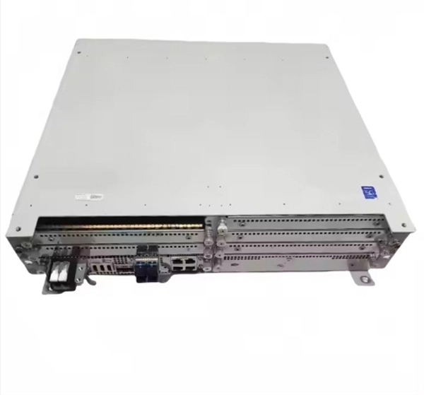
Steps for replacing the CPU module of a relay protection device
Learn the essential steps for safely removing and reinstalling a PLC CPU module to prevent equipment damage, data loss, or safety hazards. Always consult the manufacturer's documentation for model-specific instructions. Incorrect wiring may result. 1. 1 INTRODUCTION TO THE UR The GE Universal Relay (UR) series is a new generation of digital, modular, and multifunction equipment that is easily incorporated into automation systems, at both the station and enterprise levels. The application software. Manual intended for personnel responsible for installing, commissioning and using VIP protection 400. The following steps outline best practices, but always consult the. This handbook covers the code of practice in protection circuitry including standard lead and device numbers, mode of connections at terminal strips, colour codes in multicore cables, dos and donts in execution.
[PDF Version]