-
Protection of incoming and outgoing lines of primary distribution box
Typically, fuses or other devices are installed between the incoming/outgoing lines and the busbar inside the distribution box. Outdoor low-voltage power distribution boxes (hereinafter referred to as "distribution boxes") are low-voltage distribution equipment used in 380/220V power supply systems to receive and distribute electrical energy. They are generally installed at locations such as the low-voltage side of. Feeder protection plays a key role, enabling operators to prevent damage to equipment, minimize power outages, and ensure a reliable supply of electricity in medium-voltage distribution utility and industrial networks. The survey was issued in 2000 and responses were received through 2001. Jonathan Woodworth, Chair IEEE WG 3. 11) and Co-Chair of IEC TC37 MT4 (Standard 60099-4,6,8) reviews options to improve system. A well-designed distribution board types strategy is the backbone of modern electrical infrastructure, linking the incoming supply to every branch circuit in a safe and organized way. These equipment are mostly static type. Safety and protection of equipment as well as working personnel is also a considerable factor.
[PDF Version]
-
Relay Protection Design Guidelines
This handbook covers the code of practice in protection circuitry including standard lead and device numbers, mode of connections at terminal strips, colour codes in multicore cables, dos and donts in execution. This document supplements PJM Manual 07 which contains the minimum design standards and requirements for the protection systems associated with the bulk power facilities within PJM. The IEC standard for relay coordination provides clear guidelines and methodologies to ensure that protective relays work in harmony to isolate only the faulty section of the system while keeping the rest. Protective relays and devices have been developed over 100 years ago to provide “last line” of defense for the electrical systems.
-
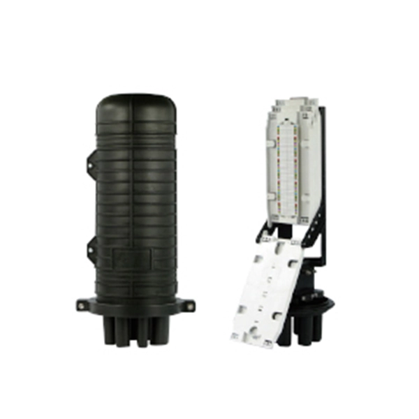
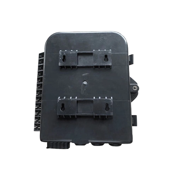
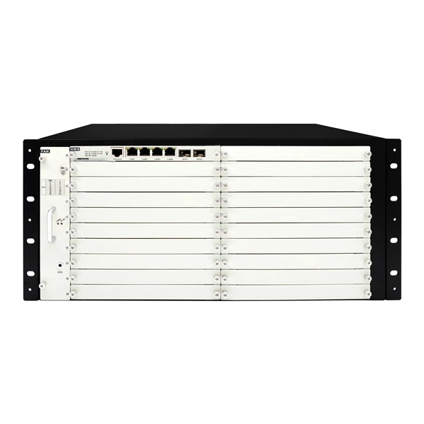
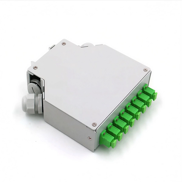
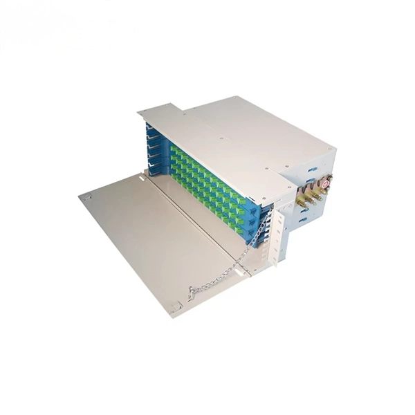
The function of the fiber optic cable protection box
They provide a secure, organized, and stable environment for the sensitive points within a fiber network—splices, connectors, and distribution points—safeguarding them from a multitude of external threats. For any organization deploying or maintaining a fiber network, understanding the role and. Fiber Connection Protection Box is a device designed for fiber optic line terminal connection and protection and is widely used in fiber optic communication systems such as fiber to the home (FTTH), local area network (LAN), and metropolitan area network (MAN). Its main functions can be summarized as follows: 1. Fiber closure protects spliced fibers in backbone and feeder lines, fiber box (or fiber distribution box) organizes and splits fibers in.
-

Distance between primary and secondary power distribution boxes
A minimum of 24 inches of cover for secondary (0 − 750 V) electric service, or 30 inches minimum cover for primary (over 750 V) is required for electric trench only. Cover is the distance from the outer surface of an underground facility to the top of the final grade. Primary distribution systems consist of feeders that deliver power from distribution substations to distribution transformers. At this. nt, and/or other requirements. ” Strict adherence to ons for manholes are critical. At a. This document is published to provide specifications, information, and guidance to assist developers in planning for and obtaining proper and prompt electric facilities to serve underground developments in the FirstEnergy Service territory. The requirements detailed in this document address conduit.
-
What are the main functions of electrical secondary relay protection
These devices detect abnormal operating conditions and initiate protective actions to isolate faults and prevent equipment damage. In other words, the prime function of protective relays is the timely and. Current transformers step down the monitored current to a secondary (output) range of 0 to 5 amps AC to power the protective relay. This prevents damage to equipment, reduces. A protection relay is an intelligent device used to monitor electrical parameters such as current, voltage, frequency, and phase angle.
-
Conventional Relay Protection Functions and Principles
The article provides an overview of protective relaying principles and their applications for high-voltage power system components. It covers the protection methods for generators, transformers, buses, and transmission lines using various relay types to detect and isolate faults efficiently. The. Also proficient in system modeling and studies with EasyPower and EMTP. Currently residing in Denver, Colorado. Based on Operating Principle Electromechanical Relays: Work using moving parts and electromagnetic forces (traditional.
-
Relay protection spring not activated due to lack of stored energy
Weak Return Spring: The spring is responsible for returning the armature to its original position. To minimize relay circuit problems and extend their lifespan, consider implementing these best practices: Proper Selection: Choose relays that match your application's voltage, current, and environmental requirements. Correct Installation: Follow manufacturer guidelines for mounting, wiring, and. Relay protection forms a critical part of electrical power network transmission and distribution systems. They act as switches, isolating control circuits from load circuits. Note: You may perform troubleshooting, but do not open the case. Failures and Assessing Causes Various problems can occur with relays in devices that use relays. In this blog, we review typical failures witnessed with.
-
The first microprocessor-based relay protection system
Schweitzer, III, invented the first microprocessor-based digital protective relay. The SEL-21 was the culmination of research done for Schweitzer's doctoral thesis, and it ushered in a new era of power system protection and went on to revolutionize the electric. In 1982, Edmund O. Schweitzer was born in. Curtiss-Wright's Nuclear Division has partnered with Schweitzer Engineering Laboratories (SEL) to serve as a channel to market for SEL's line of digital protective relays and engineering services for Commercial Nuclear markets worldwide. These relays operated based on mechanical movement, with components like coils, springs, and armatures working together to detect abnormalities in the electrical system.
-

Relay Protection Test Wiring Method
One approach to test the total protection system is to use primary injection techniques (see appendix H) that trigger protective relays and lockout relay, trip circuit breakers, and initiate annunciations and indications. If applicable, documentation is required detailing how verified protection segments overlap to ensure there is not a gap. The purpose of this Standard Work Practice (SWP) is to standardise and describe the method for testing of Ergon Energy protection relays for commissioning purposes. This SWP should be interpreted in conjunction with Standard for Substation Protection (V1. From a technician's perspective, master the unique skill of testing protection. When the transformer wiring type is Y/Y (Y0), the test wiring is very simple: when testing phase A, the tester IA is connected to the phase A of the high voltage side, and the tester IB is connected to the phase a of the low voltage side. After the neutral line of the high and low voltage sides is. Function: Use electronic components like transistors to perform switching. Applications: Frequency, undervoltage, and overcurrent protection.
[PDF Version]
-

Is selling relay protection a good business opportunity
Growing power demand, an emergent market for intelligent controllers and Increasing Demand for Electronic Devices are some of the opportunities in the global protection relay market. Pro Market Reports (PMR) excels in delivering thorough market research and detailed market analysis across a variety of industries. Firstly, the increasing demand for reliable and uninterrupted power supply, especially in emerging economies undergoing rapid industrialization and urbanization, is propelling the need for. The Global Protective Relay Market is poised for steady expansion, with a forecasted value of USD 4. 9 billion in 2024, expected to reach USD 7. Protective relays are essential components of modern power systems. A protective relay is a relay, which is considered to trip a circuit breaker when any fault is identified.
-
Wired Channel for Relay Protection
With the addition of a line tuner, the CCVT (used for potential input to the protective relay) can be used to couple the PLC signal to the power line. Protection systems are used to isolate faulted parts of the system, protect the electric system from instability, and minimize equipment damage. Directional distance and overcurrent schemes, interfaced with communication equipment, send and receive logic-based information between relay te minals to determine if the fault is external or internal to the. Important benefits include limiting tripping to faulted line section, high-speed simultaneous clearing for all internal line faults, preventing overtripping on external faults, and reducing transmission line and station damage. Applications of the concepts to accepted transmission line-protection schemes are also presented.
-

Analysis of the Four Characteristics of Relay Protection
The article first analyzes the role, composition, requirements of relay protection, and then analyzes the fault analysis of power system protection and treatment measures; the final analyzes the question of the relay protection substation operation. (1) Selectivity: refers to that when the Electrical fault occurs, the relay protection device acts and only removes the fault element. Minimize the scope of power outages as much as possible to continue the operation of non faulty parts of the system. Divide into main protection and backup. To provide effective and reliable protection to the power system, a protective relay must have the following essential functional characteristics: Selective, Fast, Stable, Reliability, Sensitivity, Simple Construction and Installation Mechanism, and Cost-effective. These are some essentially. Protective Relays - Technical Seminar Nov 2016 - Copyright: IEEE 2 Abstract: Protective relays and devices have been developed over 100 years ago to provide “lastline”of defense for the electrical systems. Therefore, the whole system has gone down, even though many circuit breakers have remained closed.
[PDF Version]