-
Power Plant Dual Relay Protection Configuration Standards
IEEE Std 242 - 2001 IEEE Buff Book–IEEE Recommended Practice for Protection and Coordination of Industrial and Commercial Power Systems IEEE Std C37. 95-2002 (R2007)Power System Protective Relays: Principles & Practices Protective Relays - Technical Seminar Nov 2016 - Copyright: IEEE 1 Power System Protective Relays: Principles & Practices Presenter: Rasheek Rifaat, P. Eng, IEEE Life Fellow IEEE/IAS/I&CPSD Protection & Coordination WG Chair Jacobs Canada. This document supplements PJM Manual 07 which contains the minimum design standards and requirements for the protection systems associated with the bulk power facilities within PJM. This document provides recommendations, background and philosophy on relay protection that is not available in M07. Consideration is given to availability and location of breakers, current sensing devices, and disconnect switches, as well as bus-switching scenarios, and their impact on the selection and application of bus protection. Its modular design and powerful DIGSI 5 engineering tool provide tailored solutions. You will get a list of all suitable products!.
[PDF Version]
-
Power Grid Optical Cable Operation Level
Key OPGW testing methods include visual inspection, OTDR testing, optical power meter testing, continuity tests, and various mechanical and environmental tests. Each method targets a specific aspect of cable performance and safety. OPGW stands for Optical Ground Wire. These cables are used on high voltage power lines. I have managed many projects where I personally oversaw the testing process. I know that if testing. This specification defines the design, material, performance and test requirements for fibre optic cable to support the fibre optic telecommunication needs. How to calculate the required fault. ion infrastructure. Optical Ground Wire (OPGW)/Underground Fiber Optic Cable (UGFO) plays a crucial role in ensuring seamless data exchange, real-time monitoring, and reliable operati n of power systems. However, with increasing demands and multiple stakeholders involved in fiber usage, it became.
[PDF Version]
-

Distance between primary and secondary power distribution boxes
A minimum of 24 inches of cover for secondary (0 − 750 V) electric service, or 30 inches minimum cover for primary (over 750 V) is required for electric trench only. Cover is the distance from the outer surface of an underground facility to the top of the final grade. Primary distribution systems consist of feeders that deliver power from distribution substations to distribution transformers. At this. nt, and/or other requirements. ” Strict adherence to ons for manholes are critical. At a. This document is published to provide specifications, information, and guidance to assist developers in planning for and obtaining proper and prompt electric facilities to serve underground developments in the FirstEnergy Service territory. The requirements detailed in this document address conduit.
-
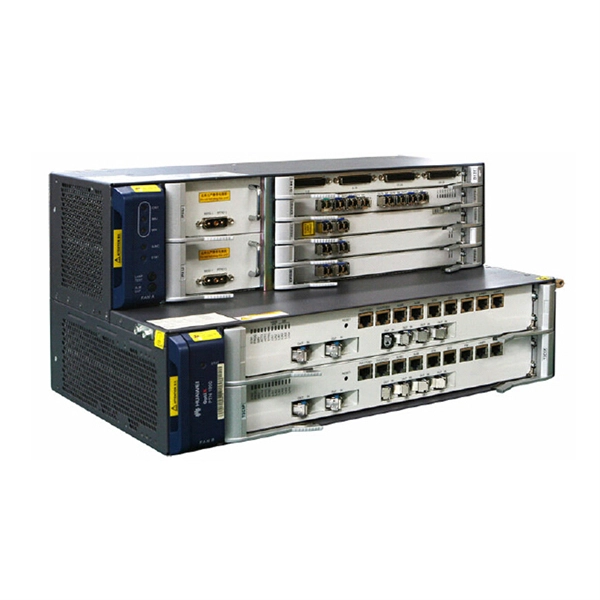
Power of Huawei optical modules
In the AI era, Huawei provides a full range of GE to 800GE optical modules, featuring three major capabilities: Spanning (ultra-long transmission), Stable (ultra-high reliability), and Secure (ultra-solid security). To address these demands, Huawei has launched the StarryLink optical module brand. This announcement occurred during the data center session titled. Describes what an optical module is and FAQs, including the fundamentals, appearance and structure, key performance counters, common types, and naming conventions of optical modules, causes of optical module failures and corresponding protection measures, types of optical modules supported by. An optical module is a component that completes electrical/optical conversion on an optical network. Huawei MA5600T series only support GPON and XG-PON; MA5800 series supports GPON, XG-PON, XGS-PON, XG-PON&GPON Combo, XGS-PON&GPON.
[PDF Version]
-
Function of the small busbar in the central power switch
The bus bar is a metal strip that distributes electrical current to the individual circuit breakers. In most assemblies you will find horizontal main bars, vertical risers, neutral and equipment-ground buses, and purpose-designed. What are Busbars, Bus Stabs, Circuit Spaces, Breaker Slots, Neutral Terminals, and Ground Terminals in an Electrical Panel or Load Center? Electric panels and load centers in residential and commercial applications have some different setting for breaker installation ad load circuit distribution. They connect directly to the main power source and are designed to handle high current loads safely. Circuit Breakers act as protective devices within the panel.
-
Increase the light output power of the optical module
An optical amplifier is a device which receives some input signal light and generates an output signal with higher optical power. Typically, inputs and outputs are laser beams (very rarely other types of light beams), either propagating as Gaussian beams in free space or in a fiber. At the receiver end, the optical signals are reconverted into electrical. In this guide, we will explain what optical signal strength is, how to check it on Cisco IOS using the command line, and how to troubleshoot common light level issues. Assume the. This application note gives a short introduction to optical modules and the need of an optimized power tree in them and then concentrates on the use cases and benefits of four-switch and inverting buck-boost converters inside optical modules.
-
The high-voltage distribution box shows no power as indicated by the power meter
Be sure that the power distribution box has sufficient power provided to it. Long cable runs can result in a voltage drop, which can be solved by using a heavy gauge wire. Understanding how to. This outlet won't give any power, but the little light is on and will react to a voltage tester, any idea? Archived post. PDUs can vary from basic power strips to sophisticated units with surge protection and monitoring capabilities. This exterior enclosure houses the instrument that measures electrical energy consumed, recorded in kilowatt-hours (kWh).
-
Optical module test power not adjusted too low
What does it mean if the transmitted power is too low? Low transmitted power can mean the connectors are dirty. Clean the connectors, check the module, and look at the fiber. If it still does not. Stable optical power is the foundation of every high-capacity optical transport system. Even minor deviations—whether too high, too low, or unstable—can impact signal integrity, trigger service alarms, or interrupt traffic on DWDM, OTN, or long-haul optical line systems. Because optical networks. The article Digital Diagnostic Function (DDM) For Optical Modules describes that DDM function can be used for real-time monitoring and fault location of the module's working status, in which the optical module's transmitting optical power and receiving optical power are the key parameters for. To test transmitted power in sfp optical modules, you use an optical power meter to get exact results. Many sfp modules also have DOM/DDM, which lets you see digital diagnostic monitoring data on network equipment. Built into modern SFP/SFP+/ SFP28 /QSFP family modules and standardized by SFF-8472, DDM/DOM exposes real-time values for the module's temperature, supply.
[PDF Version]
-
Equipment parameters of optical power meter
Fiber optic power meters measure the average optical power out of an optical fiber. Power meters typically consist of a solid state detector (silicon for short wavelength systems, germanium or InGaAs for long wavelength systems), signal conditioning circuitry and a digital display of. An optical power meter (OPM) is a device used to measure the power in an optical signal. In this article, learn: What is an optical power meter? An optical power meter (OPM) measures the power levels of light signals in devices that transmit data or power using. Testing fiber optic components and cable plants requires making several measurements with the most common measurement parameters listed in the Table below. To augment the absolute power measurements NIST provides nonlinearity, spectral responsivity, and uniformity measurements.
-
What type of fiber optic cable is used for power transmission towers
Optical Ground Wire (OPGW) cable is a type of fiber optic cable that is specifically designed for use in overhead power transmission lines. These cables are made up of extremely thin strands of glass or plastic, known as optical fibers, which are encased in protective sheathing. The fibers are arranged in. Besides the use of special cables on transmission and distribution towers or poles, the installation of fiber optic cables for utilities may require the shutdown of electrical distribution for installation, although some installations are possible without shutdown. Such cable combines the functions of grounding and telecommunications. The all-dielectric design eliminates.
-
What is a normal power rating for pigtails
A well-constructed 8-pin cable, such as our PSU cables with pigtail connectors, should be well capable of providing more than 300W of power. In the world of temporary power, a pigtail is typically a short power cord with a connector on one end, and either a bare wire or another type of termination on the other. The extra 2 pins are two wires simply acting as "sense" wires that notify the GPU of the capability to draw 150W. It ensures a secure connection by combining wires with a wire connector, like a twist-on connector or a wire nut, and then linking them to the intended. The American Wire Gauge (AWG) system is a standardized method for measuring wire diameter, where smaller numbers indicate thicker wires. The AWG system works logarithmically – each 3-gauge. The key to choosing the right pigtail connector is to match it to your needs. A connector that is too small or too large can result in a weak or loose connection. Voltage and Current: Check the voltage. avy wall annealed copper tube with a 250 psig pressure rating. The 1/4” and 3/8” ube have a pull test rating of 500 and 750 p applications require specific pigtail and hogtail assemblies.
[PDF Version]