-
PoE switch network stability
PoE switches provide a stable and reliable network experience through wired connections, avoiding the interference issues of wireless signals. They use dedicated pairs of wires to separately transmit power and data, ensuring that network performance is not affected by the power. Power over Ethernet (PoE) switches are essential in many network setups, providing data and power over a single cable. However, the power supply stability of PoE switches directly affects the reliability. We have a SIP PoE phone system and we seem to be starting to have more complaints than usual with some phones malfunctioning. Here, we will list some common factors in this article. Therefore, everyone is concerned about whether PoE switches will affect speed.
-
Can PoE power be turned off on a PoE switch
For TP-Link PoE switches, except for Unmanaged Switches, we can disable/enable PoE power on individual ports under PoE > PoE config, and PoE Status of PoE port is enabled by default settings. 08-27-2024 07:21 AM Just so we are confusing folks - We don't turn off switch port just to turn off PoE. To disable PoE only for an interface, go. Please note that the TL-SG108 doesn't support PoE at all. If a device does not need PoE the switch/UDM will not supply any power on that port. In the Network Operations app, select one of.
-
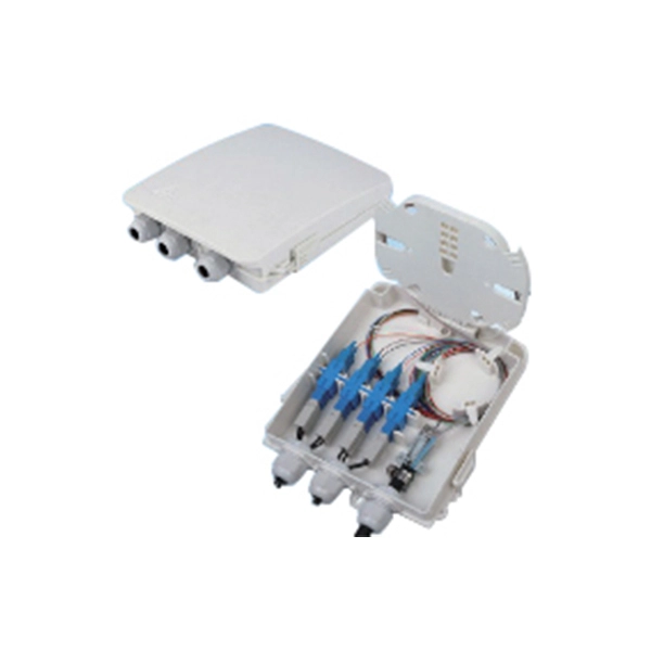
How to connect a switch to a fiber optic network
Most modern fiber-enabled network switches require an SFP transceiver module featuring a duplex (two strand) multimode OM3 or duplex single mode OS2 connection with LC connectors. Direct attach cables with pre-terminated SFP connections may also be used. SFP transceiver modules are specific to the type of fiber being connected. Fiber optic cabling is increasingly used to connect network switches and other datacom equipment, especially in long-distance and mission-critical applications. Fiber provides: Increased internet signal bandwidth.
-
Function of the small busbar in the central power switch
The bus bar is a metal strip that distributes electrical current to the individual circuit breakers. In most assemblies you will find horizontal main bars, vertical risers, neutral and equipment-ground buses, and purpose-designed. What are Busbars, Bus Stabs, Circuit Spaces, Breaker Slots, Neutral Terminals, and Ground Terminals in an Electrical Panel or Load Center? Electric panels and load centers in residential and commercial applications have some different setting for breaker installation ad load circuit distribution. They connect directly to the main power source and are designed to handle high current loads safely. Circuit Breakers act as protective devices within the panel.
-
Normal optical power of the switch
Transmit power is typically good when it is in the 6 dB range between -1 and -7 dBm. Have you ever encountered a Cisco switch interface that constantly flaps (goes up and down) or suddenly enters an err-disabled state? Before you blame the switch or replace the cable, you need to look at the invisible data: the light levels. If either Tx or Rx is in the -30 dBm or lower range that's usually indicative of there being no actual signal received and the transceiver is reporting. When designing optical networks, understanding the TX/RX power range is vital for ensuring optimal performance and long-term reliability. All ports below are 10gbps 850nm sm. See the one for port 2:59 has a * (star) next to RxPower. The reliability of this transmission depends entirely on the strength of that light signal as it reaches its destination.
-
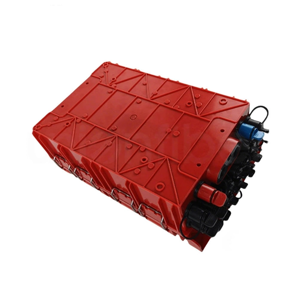
Inspect the power distribution box switch box for faults
Check the electrical load and ensure that the sensors do not exceed the 10 Amp maximum. Power distribution & circuit protection depend on it. LV intrusive switchboards accept power from the utility & generator & distribute it to building circuits. Ensure that all labels and warning signs are legible. Internal Inspection Open the distribution box and check for. Diagnose the fault in a low voltage distribution box by checking for overheating, loose connections, and using voltage testers for safe troubleshooting.
-
Switch for two optical and four electrical ring network
This industrial ring network switch is equipped with 2 gigabit SC optical fiber interfaces and 4 gigabit Ethernet electrical ports. Its network mode can form a closed loop. Its design is aimed at meeting the requirements of industrial. 4 * 10/100/1000Mbps RJ45 ports+2 * Gigabit SFP ports (uplink) FW104GS-2F is an industrial full gigabit management Ethernet switch, which supports APOLLO visual cloud management, operation and maintenance. The equipment can be managed, operated and maintained through mobile terminal, PC terminal and. Use high-quality photoelectric integrated modules to provide good optical and electrical characteristics Ensure reliable data transmission and long working life Support full-duplex or half-duplex mode with auto-negotiation capability The network port supports automatic cross-recognition Built-in. BL167GM-SFP is a managed industrial Ethernet switch with 2 Gigabit SFP and 4 Gigabit RJ45 ports, compliant with FCC, CE, and RoHS. It supports key Layer 2 protocols for stable communication, features fanless low-power design, wide -40°C to +75°C temperature range, and strong EMC performance.
[PDF Version]
-
Can a ring network function without a core switch
A ring network is a in which each node connects to exactly two other nodes, forming a single continuous pathway for signals through each node – a ring. Data travels from node to node, with each node along the way handling every packet. Rings can be unidirectional, with all traffic travelling either clockwise or counterclockwise around the ring, or bidirectional (as in ). Because a un.